Input Amplifier
The instructions in this section are consecutive. Do not change a set
-
ting until you are told to do so, either in the text or in the tables.
n
Setup
–
Remove the screen shield before performing any adjustments
in the input amplifier.
–
Connect the counter to line power.
–
Switch on the counter.
–
Press PRESET, then press ENTER.
Offset
–
Connect the DMM to Pin 10 of U8 and GND = screen, see
Fig. 6-2. Pin 1 is marked in the figure and is the middle pin on
the side closest to the rear of the unit. Alternatively you can
use one of the soldering pads of resistor R114 as a test pad, as
it is connected to Pin 10. This resistor is normally not
mounted.
–
Adjust R33 = OFFSET A until the DMM reads 0.0 ±0.2 mV.
Linearity
n
Setup
–
Press the Waveform Key once. (This step puts the instrument
into the correct mode so that it switches from x1 Attenuator to
x11 Attenuator when the sensitivity is adjusted above 2.8V.)
–
Connect the pulse generator to the A input of the counter via
the power splitter.
–
Connect the other output from the power splitter to channel A
of the oscilloscope.
NOTE: The Pulse Generator with 50 ohm output impedance
should be set to 5 V
pp
when loaded in 50 W, so that the
level recorded at the CRO A channel (equal to the in
-
put to the DUT) is 2.5 V
pp
, after going through the split
-
ter.
NOTE: If you are using a 10 MW x10 CRO probe, ensure that
its compensation has been correctly adjusted, so that
incorrect observations of undershoots/overshoots are
not made.
–
Use the probe to connect channel B of the oscilloscope to
Pin 10 of U8 .
–
Adjust R31 = LIN A until both signals look as alike as possi
-
ble.
NOTE: The AC coupling will give the curve a slight tilt.
x1 Attenuator
n
Setup
–
Adjust C2 = X1 until both signals on the screen look as alike
as possible, without any overshoots or undershoots. The level
displayed on the CRO B channel for Pin 10 of U8 is approxi
-
mately 1.2 V
pp
.
x11 Attenuator
n
Setup
–
Adjust C1 = X11 until both signals on the screen look as alike
as possible, without any overshoots or undershoots.
Input Amplifier 6-3
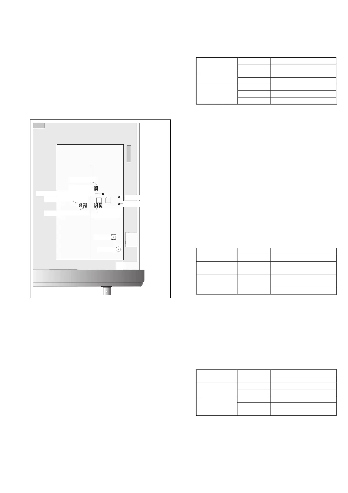
Offset A (R33)
ZERO ADJ. COMP I
Li n A (R31)
X11 (C1)
X1(C2)
TP10, T R IG L E VE L COMP I
TP11, TRIG LEVEL COM
ZERO ADJ.COMP II
TP27
1
13
,SENSE
SenseAdj.
TP26, SENSE
J2 U8
Fig. 6-2 Test points and trimmers for the Input amplifiers.
PM6685
Input A 50 W
Sensitivity Any level below 1 V
rms
Pulse generator
Amplitude 5V
pp
in 50 W
Period 2 ms, symmetrical
Oscilloscope
Time 200 ms/div
Setting: A 0.5 V/div, 50 W,DC
Setting: B 20 mV/div, 10:1 probe, DC
Table 6-2
PM6685
Impedance 50 W
Sensitivity Any level below 1 V
rms
Pulse generator
Amplitude 5V
pp
in 50 W
Period 100 ms, symmetrical
Oscilloscope
Time 10 ms/div
Setting: A 0.5 V/div, 50 W,DC
Setting: B 20 mV/div, 10:1 probe, DC
Table 6-3
PM6685
Impedance 50 W
Sensitivity Any level above 2.8 V
rms
Pulse generator
Amplitude 5V
pp
Period
100 ms, symmetrical
Oscilloscope
Time 10 ms/div
Setting: A 0.5 V/div, 50 W,DC
Setting: B 5 mV/div, 10:1 probe, DC
Table 6-4