PM6685R
Introduction
A Rubidium timebase is now available for the PM6685 Frequency
counter. This oscillator cannot be retrofitted in the standard version
of the PM6685. Due to the size of the timebase and its power require
-
ments, a larger cabinet must be used.
A fan is needed to keep the temperature to an acceptable level.
This version is called PM6685R, where “R” stands for Rubidium.
Performance Check
Required Test Equipment
NOTE: To fully test the accuracy of the PM6685R, access to
an extremely high stability reference signal is needed,
for example a Cesium atomic reference or a transmit
-
ted signal from a nationally or internationally traceable
source. Additionally the instrument has to be stabilized
for a period of one month.
The PM6685R is equipped with an LED labelled “UNLOCKED”.
When the LED is lit the Rubidium time base is still in its warm-up
phase and is not yet stabilized.
Test procedure
–
Connect the counter to the line power.
–
Check that the UNLOCK LED is lit.
–
Check that the UNLOCK LED is switched off within £ 6
minutes after connection to line power.
–
Connect a 10 MHz reference signal to input A of the counter.
–
Select FREQUENCY A measurement.
–
Select 1 s measuring time.
–
Check that the displayed frequency is 10.00000000 MHz
±1 LSD < 6 minutes after connection to line power.
Functional Description
The oscillator is supplied with 24 V from the extra power supply.
The oscillator generates a stable 10 MHz output frequency from a
20 MHz Voltage Controlled Crystal Oscillator (VCXO), whose fre
-
9-12 Introduction
Type Performance Model
10 MHz reference £1x10
-10
Calibrated Rubidium
oscillator or Cesium
atomic standard
Table 9-4 Required test equipment
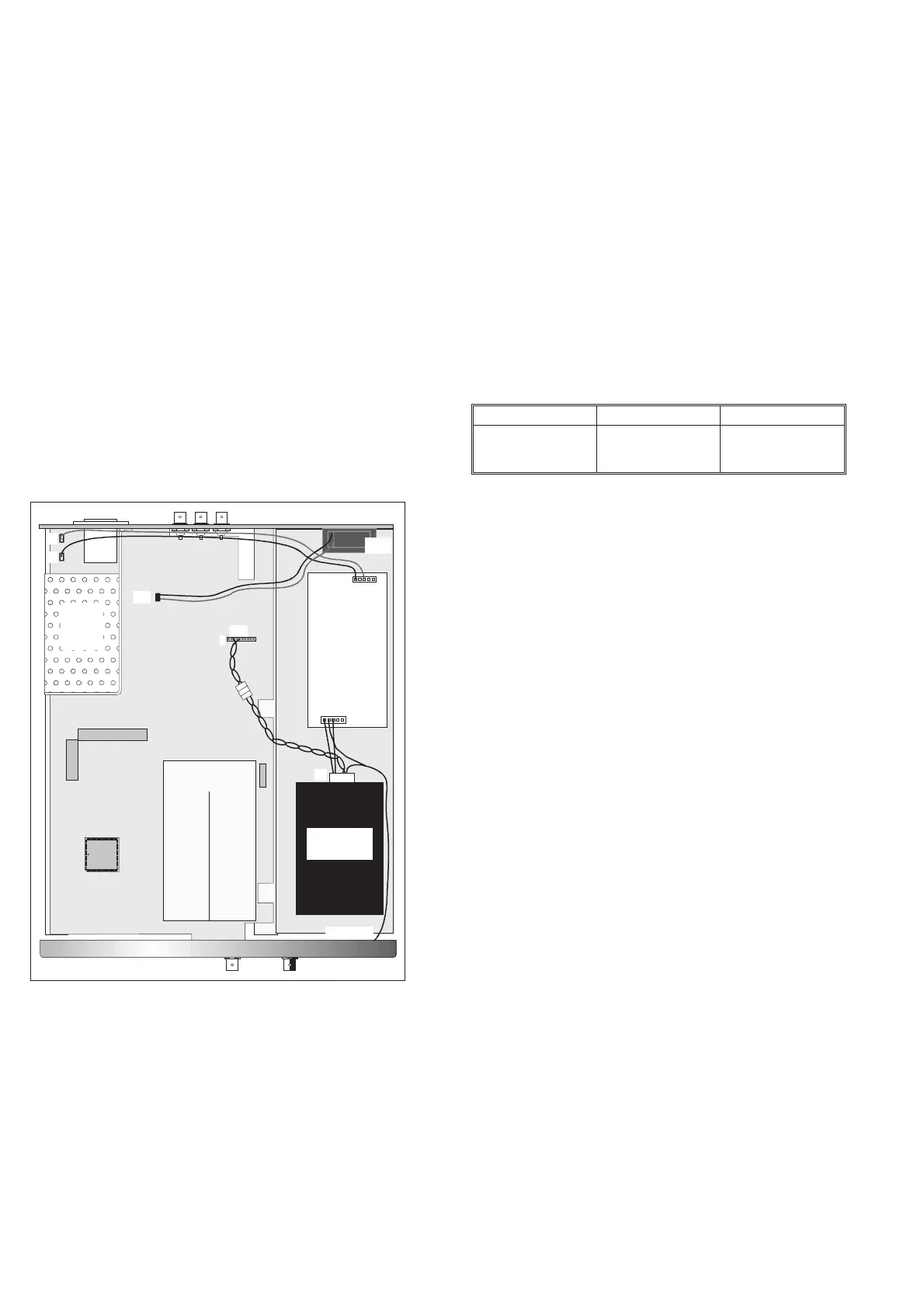
Main
Power
Supply
J3
Fan
Rubidium
Timebase
J4
P2
P3
J24
P1
Aux Power
Supply
1
Freq. Adj.
1
J31
1
Fig. 9-12 Location of the Rubidium Timebase and its power
supply.