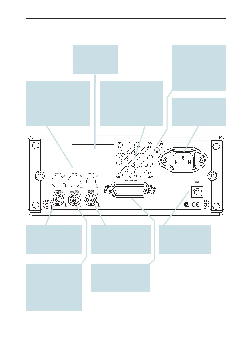
Rear Panel
Secondary Controls 2-5
Using the Controls
!
!
!
191125
GPIB Connector
Address set via User Op
-
tions Menu.
USB Connector
Universal Serial Bus
(USB) for data commu
-
nication with PC.
External Reference
Input
Can be automatically se
-
lected if a signal is pres
-
ent and approved as
timebase source, see
Chapter 9.
External Arming Input
See page 5-7.
Reference Output
10 MHz derived from the
internal or, if present, the
external reference.
Line Power Inlet
AC 90-265 V
RMS
,
45-440 Hz, no range
switching needed.
Fan
A temp. sensor controls the
speed of the fan. Normal
bench-top use means low
speed, whereas rack-mount
-
ing and/or options may result
in higher speed.
Optional Main Input
Connectors
The front panel inputs can
be moved to the rear panel
by means of an optional ca
-
ble kit. Note that the input
capacitance will be higher.
Protective Ground
Terminal
This is where the pro
-
tective ground wire is
connected inside the in
-
strument. Never tamper
with this screw!
Type Plate
Indicates instrument
type and serial
number.
 Loading...


