2.
After resetting the air intake restriction indicator
during the daily pretrip inspection, check the indi-
cator again with the engine off.
2.1
Check an indicator with graduations to see
if air restriction exceeds the value shown
in Table 21.2.
Check a go/no-go indicator without gradu-
ations to see if the colored bar shows
through the clear window.
Air Intake Maximum Restriction Values (inH
2
O)
Engine Make
Pre-EPA07
Engines
EPA07 and
Newer Engines
Cummins 25 25
Detroit 20 22
Mercedes-Benz 22 22
Table 21.2, Air Intake Maximum Restriction Values
2.2
If air restriction exceeds the maximum al-
lowable value, operate the vehicle for one
more day, making sure not to run the en-
gine over rated rpm. Refer to the engine
operation manual for more information on
rated rpm for your engine.
2.3
If air restriction exceeds the maximum
value again, replace the air cleaner. For
instructions, refer to Group 09 of the Cas-
cadia Workshop Manual.
3.
Inspect water evacuation components.
3.1
Inspect the vacuator valve(s) installed on
the hood interior and air cleaner. Make
sure the lips of each valve are undam-
aged and pliable, free of debris, and re-
main closed during inspection. See
Fig. 21.12 and Fig. 21.13.
3.2
Inspect the rain tray installed at the base
of the windshield. Ensure that the seal on
the forward edge of the rain tray is in
good condition.
3.3
Inspect the drain hoses installed on the
rain tray. Both hoses should be securely
attached to the rain tray and direct water
down the aft side of the front fenders. See
Fig. 21.14.
4.
If the vehicle is equipped with an Allison auto-
matic transmission, check the automatic trans-
mission fluid level.
5.
Check for water in the fuel/water separator, if
equipped.
IMPORTANT: When draining fluid from a
fuel/water separator, drain the fluid into an
appropriate container and dispose of it prop-
erly. Many jurisdictions now issue fines for
draining fuel/water separators onto the
ground.
5.1
Place a suitable container under the fuel/
water separator.
NOTE: A hose may be used to direct water
into the container. Use a hose with a ½-inch
pipe thread on DAVCO models.
5.2
If the engine is equipped with a built-in
water separator, loosen the drain valve,
and allow the water to run out. Close the
drain valve, taking care not to overtighten
it.
5.3
Alliance/Racor Models: Turn the drain plug
counterclockwise to open it. See
Fig. 21.15.
DAVCO Models: Remove the vent cap
and open the drain. See
Fig. 21.16.
5.4
Stop draining fluid when fuel begins to
drain out.
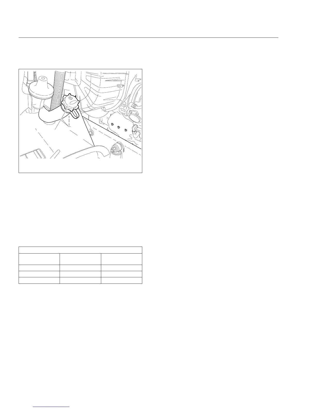
05/21/2007 f820442
1
1. Washer Fluid Filler Cap
Fig. 21.11, Windshield Washer Reservoir
Pre- and Post-Trip Inspections and Maintenance
21.11