RXB PLUS ROTARY SCREW COMPRESSOR UNITS S70-101 IOM
Page 11
INSTALLATION
1. The thermosyphon oil cooler is supplied with the oil side piped to the compressor unit and stub ends supplied on the refriger-
ant side.
2. A three-way oil temperature control valve is required where condensing temperature is expected to go below 65
O
F.
3. A refrigerant-side safety valve is required in this location only when refrigerant isolation valves are installed between the cooler
and thermosyphon receiver. If no valves are used between the cooler and TSOC receiver, the safety valve on the TSOC receiver
must be sized to handle the volume of both vessels. Then, the safety valve on the cooler vent (liquid refrigerant side) can be
eliminated.
4. The system receiver must be below the thermosyphon receiver in this arrangement.
Current thermosyphon systems are using two-pass oil cool-
ers and flow rates based on 4:1 overfeed.
The liquid/vapor returned from the cooler is separated in the
receiver. The vapor is vented to the condenser inlet and need
only be reliquified since it is still at condenser pressure.
INSTALLATION - The shell and tube-type thermosyphon oil
cooler with oil-side piping and a thermostatically controlled
mixing valve (if ordered) are factory mounted and piped. The
customer must supply and install all piping and equipment
located outside of the shaded area on the piping diagram
with consideration given to the following:
1. The refrigerant source, thermosyphon or system receiv-
er, should be in close proximity to the unit to minimize piping
pressure drop.
2. The liquid level in the refrigerant source must be 6 to 8
feet above the center of the oil cooler.
3. A safety valve should be installed if refrigerant isolation
valves are used for the oil cooler.
4. Frick recommends the installation of an angle valve in the
piping before the thermosyphon oil cooler to balance the
thermosyphon system. Frick also recommends the installa-
tion of sight glasses at the TSOC inlet and outlet to aid in
troubleshooting. The factory-mounted, plate-type ther-
mosyphon oil cooler requires a refrigerant-side drain valve
to be provided and installed by the customer.
TSOC AND WCOC OPTIONAL OIL SIDE SAFETY RELIEF
- Compressor units, which have valves in the oil piping to
isolate the oil cooler from the oil separator for servicing,
may have factory installed piping to relieve the shell side
(oil side) safety valve directly into the oil separator, as shown
in the P & I diagrams on pages 58 through 60.
This arrangement uses a special UV stamped safety valve
rated for liquid and vapor relief. The safety valve is designed
for 500 psi DWP and is set to relieve at 75 psi delta P. The
safety valve piping contains flanged connections should the
valve require maintenance or replacement.
Extra caution should be used when servicing an oil sepa-
rator with this arrangement. If the oil cooler is valved off
from an oil separator which has been evacuated for ser-
vicing, then the oil cooler could relieve into the separa-
tor vessel if the 75 psi delta p setpoint is exceeded.
Other units, which do not use this special safety valve ar-
rangement, will have factory mounted safety valves on the
shell side of the oil cooler which the installing contractor
should pipe into house safety systems designated suitable
for oil relief.
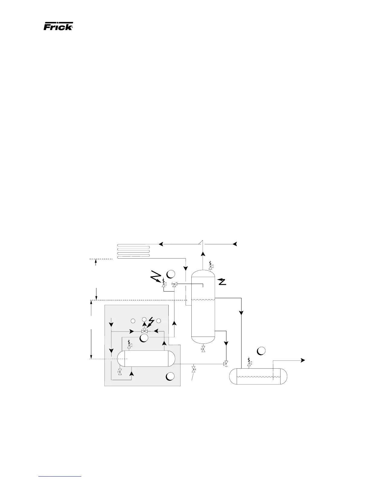
The component and piping arrangement shown below is in-
tended only to illustrate the operating principles of thermosy-
phon oil cooling. Other component layouts may be better suited
to a specific installation. Refer to publication E70-900E for ad-
ditional information on Thermosyphon Oil Cooling.
B
C
A
OIL TEMP
CONTROL VALVE
HOT
COOL
OIL OUT
HOT OIL IN
THERMOSYPHON
OIL COOLER
LIQUID
LEVEL
STATIC HEAD
TO OVERCOME
CONDENSER
PRESSURE DROP
8 Ft.
Min.
SYSTEM
CONDENSER
SAFETY
VALVE
VAPOR
THERMOSYPHON
RECEIVER
LIQUID OVERFLOW
DRAIN TO RECEIVER
TO SYSTEM
EVAPORATOR
SYSTEM
RECEIVER
1
3
4
(Mounted below Thermosyphon
receiver level)
2
TSOCA
Refrigerant-side drain valve
required for plate-type
thermosyphon oil coolers.