RXB PLUS ROTARY SCREW COMPRESSOR UNITSS70-101 IOM
Page 26
OPERATION
AT 158
O
F.
The microprocessor triggers the High Oil Temperature Alarm
and displays the alarm on the Operating display and the
Annunciator display.
AT 167
O
F.
The microprocessor instructs the compressor motor to shut
down and displays a CUTOUT indication on the Operating
display. It stores the operating conditions at the moment of
OUTPUT NO.
TERMINAL NO.
MNEMONIC
Compressor Off
Running
Slide
Valve
Position
HEX
CODES
13
34
BIT
0
0
1
0
1
0
1
0
1
0
1
0
33
14
BIT
1
0
15
32
BIT
2
0
16
31
BIT
3
0
MEANING OUTPUT DATA CODE
Running with MLC Inhibit
Lockout on Recycle Delay
Cutout
Undefined
Undefined
1101
0011
1011
0111
1111
B
C
D
E
F
10%
20%
30%
40%
50%
60%
70%
80%
90%
100%
0
0
0
0
1
1
1
1
0
0
0
0
0
0
0
0
0
0
1
1
1
0
1
1
0
0
1
1
0
0
1
1
2
3
4
5
6
7
8
9
A
cutout in the Freeze display. Information regarding the cut-
out will also be retained by the Annunciator and the Shut-
down Record displays.
NOTE: If the operator makes an error by attempting to
start the compressor under conditions outside safe
normal operating conditions, the microprocessor will
prevent start-up and advise the operator of the fault.
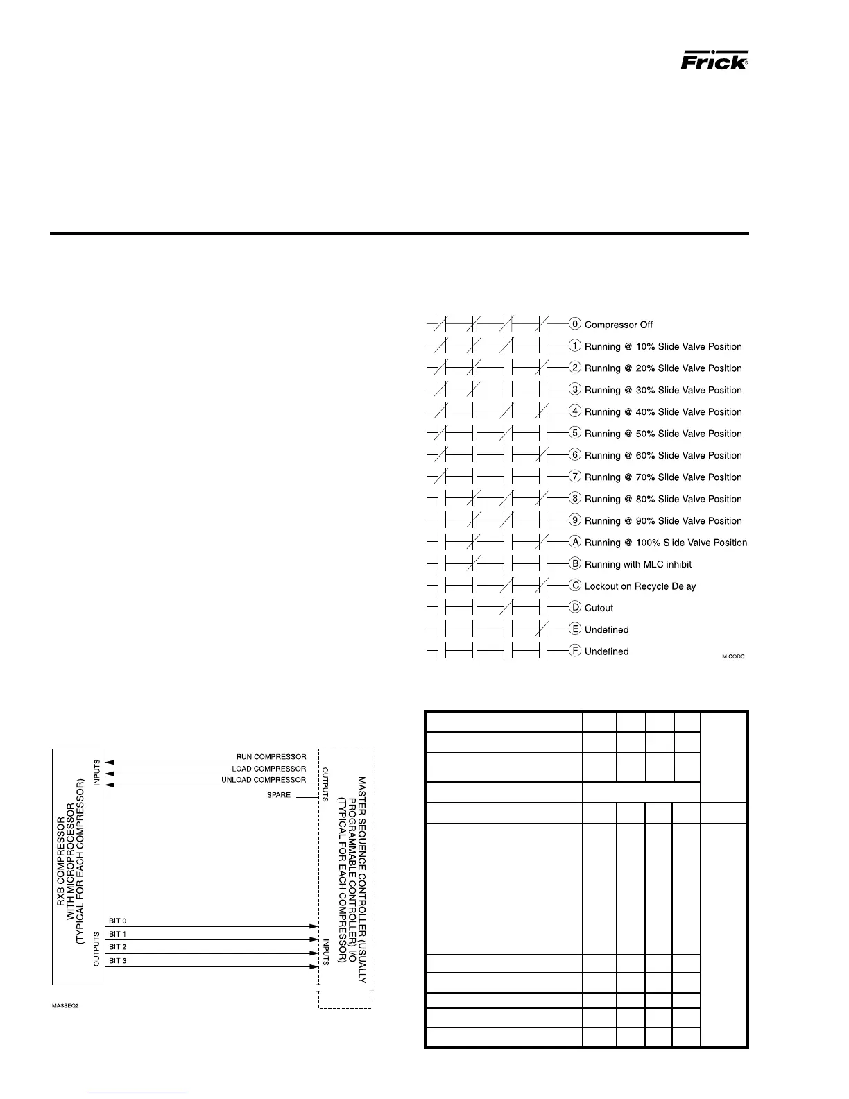
MULTIPLE COMPRESSOR SEQUENCING
FOR RXB COMPRESSOR UNITS WITH
MICROPROCESSOR CONTROLS
A - The standard microprocessor panel includes:
1. Remote Run Input
2. Remote Load Input
3. Remote Unload Input
The remote run input is only recognized when the remote
run mode has been selected by pressing the [REMOTE
START] key on the front panel of the microprocessor.
The remote load and unload inputs can only be recognized
when the [REMOTE] key in the slide valve column on the
front panel of the microprocessor has been pressed.
B - If master sequencing between multiple compressors in
parallel on a common suction is desired. This output data
will permit the compressor microprocessor to be interfaced
with a master sequence controller. See electrical diagram
for details.
C - A master sequence controller must be installed to pro-
vide the signals to remote start and stop the compressors
and remote load and unload the compressors based on the
common suction pressure or other parameter and the com-
pressor status based on the optional microprocessor out-
put data feedback. The customer may supply his own mas-
ter sequencer panel (usually a programmable controller) or
Frick, can supply this sequencer if desired (contact Frick
Company for pricing).
SUGGESTED PROGRAMMABLE
CONTROLLER PROGRAM TO DECODE
MICROPROCESSOR OUTPUT DATA CODES