RXB PLUS ROTARY SCREW COMPRESSOR UNITSS70-101 IOM
Page 4
FOUNDATION
Each RXB PLUS Rotary Screw Compressor Unit is shipped
mounted on a wood skid which must be removed prior to unit
installation. CAUTION: Allow space for servicing both ends
of the unit. A minimum of 24 inches is recommended.
The first requirement of the compressor foundation is that it
must be able to support the weight of the compressor pack-
age including coolers, oil, and refrigerant charge. Screw
compressors are capable of converting large quantities of
shaft power into gas compression in a relatively small space
and a mass is required to effectively dampen these rela-
tively high frequency vibrations.
Firmly anchoring the compressor package to a suitable foun-
dation by proper application of grout and elimination of pip-
ing stress imposed on the compressor is the best insurance
for a trouble free installation. Use only the certified general
arrangement drawings from Frick to determine the mount-
ing foot locations and to allow for recommended clearances
around the unit for ease of operation and servicing. Foun-
dations must be in compliance with local building codes and
materials should be of industrial quality.
The floor should be a minimum of 6 inches of reinforced con-
crete and housekeeping pads are recommended. Anchor bolts
are required to firmly tie the unit to the floor. Once the unit is
rigged into place (See HANDLING and MOVING), the feet must
then be shimmed in order to level the unit. The shims should
be placed to position the feet roughly one inch above the house-
keeping pad to allow room for grouting. An expansion-type
epoxy grout must be worked under all areas of the base with
no voids and be allowed to settle with a slight outward slope so
oil and water can run off of the base.
When installing on a steel base, the following guidelines should
be implemented to properly design the system base:
1. Use I-beams in the skid where the screw compressor will be
attached to the system base. They should run parallel to the
package feet and support the feet for their full length.
2. The compressor unit feet should be continuously welded to
the system base at all points of contact, or bolted.
3. The compressor unit should not be mounted on vibration
isolators in order to hold down package vibration levels.
4. The customer’s foundation for the system base should fully
support the system base under all areas, but most certainly
under the I-beams that support the compressor package.
When installing on the upper floors of buildings, extra pre-
cautions should be taken to prevent normal package vibra-
tion from being transferred to the building structure. It may
be necessary to use rubber or spring isolators, or a combi-
nation of both, to prevent the transmission of compressor
vibration directly to the structure. However, this may increase
package vibration levels because the compressor is not in
contact with any damping mass. The mounting and support
of suction and discharge lines is also very important. Rub-
ber or spring pipe supports may be required to avoid excit-
ing the building structure at any pipe supports close to the
compressor package. It is best to employ a vibration expert
in the design of a proper mounting arrangement.
In any screw compressor installation, suction and discharge lines
should be supported in pipe hangers (preferably within 2 ft. of
vertical pipe run) so that the lines won’t move if disconnected
from the compressor. See table for Allowable Flange Loads.
A licensed architect should be consulted to determine the
proper foundation requirements for any large engine or tur-
bine drive.
INSTALLATION
NOZ.
SIZE
NPS
(in.)
AXIAL VERT. AXIAL VERT. LAT.LAT.
M
R
M
C
M
L
PV
C
V
L
1
1.25
1.5
2
3
4
5
6
8
10
12
14
50
50
75
125
250
400
450
650
900
1200
1500
2000
50
50
75
125
250
400
450
650
900
1200
1500
2000
50
50
100
150
225
300
400
650
1500
1500
1500
1700
25
25
40
70
175
200
400
750
1000
1200
1500
1800
25
25
40
70
175
200
400
750
1000
1200
1500
1800
25
25
50
100
250
400
425
1000
1500
1500
1500
2000
ALLOWABLE FLANGE LOADS
MOMENTS (ft-lbf) LOAD (lbf)
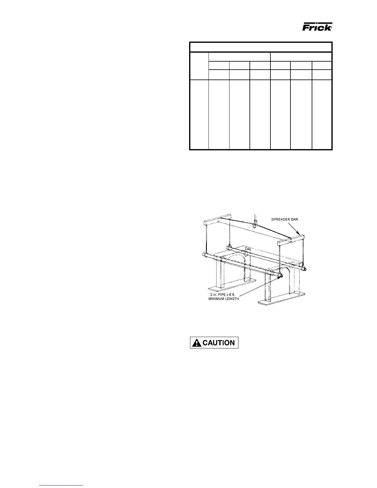
HANDLING AND MOVING
THIS UNIT MAY BE TOP HEAVY.
USE CARE WHILE HANDLING.
Spreader bars should be used on
both the length and width of the package to prevent
bending of oil lines and damage to the package.
The unit can be moved with rigging, using a crane or forklift.
The recommended method is to insert lengths of 2" pipe
through the lifting holes in the vertical supports (see FIG. 1).
Alternatively, hooks may be used in rigging, inserting them
in the lifting holes (see FIG. 2).
Use CAUTION in locating the lifting ring. If no motor is
mounted, the lifting ring should be moved off center to the
compressor side of the unit because 60 percent of the weight
is toward the compressor end. If a motor is mounted, ap-
propriate adjustment in the lifting point should be made to
compensate for motor weight. Adjustment of the lifting point
must also be made for any additions to the standard pack-
age, such as an external oil cooler, etc., as the center of
balance will be affected.
FIG. 1 - RECOMMENDED LIFTING METHOD
When applying screw compressors at high pressures, the
customer must be prepared for package vibration and noise
higher than the values predicted for normal refrigeration duty.
Proper foundations and proper installation methods are vi-
tal; and even then, sound attenuation or noise curtains may
be required to reduce noise to desired levels.
For more detailed information on Screw Compressor Foun-
dations, please request Frick publication S70-210 IB.