RXB PLUS ROTARY SCREW COMPRESSOR UNITSS70-101 IOM
Page 10
OIL COOLER DATA TABLE
SIZE - Inches APPROX
WATER FLOW
COOLER WATER CONN RANGE (GPM)
5 Foot Lengths
6" DIA. 1 NPT 10 – 23
8" DIA. 1-1/4 NPT 35 – 60
* 100 ft. liquid line. For longer runs, increase line size ac-
cordingly.
Liquid line sizes and the additional receiver volume (quan-
tity of refrigerant required for 5 minutes of liquid injection oil
cooling) are given in the following table:
LIQ. LINE SIZE* FLOW LIQUID
REF RXB RATE VOLUME
MODEL PIPE TUBING (lb.) CU.FT.
SCH 80 OD 5 MIN
12 1/2 – 10 .3
15 1/2 – 12.5 .4
HIGH 19 1/2 – 15 .4
STAGE 24 1/2 – 20 .6
R-717 30 1/2 – 25 .7
39 1/2 – 30 8
50 3/4 – 40 1.1
12 3/4 5/8 30 .4
15 3/4 5/8 37.5 .5
HIGH 19 3/4 5/8 45 .6
STAGE 24 3/4 7/8 60 .8
R-22 30 3/4 7/8 75 1.0
39 3/4 7/8 95 1.3
50 1 1 125 1.7
12 1/2 – 2.1
15 1/2 – 2.5 .1
BOOST- 19 1/2 – 3.5 .1
ER 24 1/2 – 4.5 .1
R-717 30 1/2 – 5.5 .2
39 1/2 – 6.5 .2
50 1/2 –- 8.5 .3
12 3/4 1/2 6 .1
15 3/4 1/2 7 .1
BOOST- 19 3/4 1/2 9 .1
ER 24 3/4 1/2 12 .2
R-22 30 3/4 1/2 14.5 .2
39 3/4 1/2 18 .3
50 3/4 5/8 24 .3
WATER-COOLED OIL COOLING (OPTIONAL)
The shell and tube-type, water-cooled oil cooler is mounted
on the unit complete with all oil piping. The customer must
supply adequate water connections and install the two-way
water regulating valve. It is recommended that (local codes
permitting) the water regulator be installed on the water outlet
connection. Insert the water regulator valve bulb and well in
the chamber provided on the oil outlet connection. Deter-
mine the size of the water-cooled oil cooler supplied with
the unit, then refer to table for the water connection size
and water flow range (GPM). The water supply must be
sufficient to meet the required flow.
It is imperative that the condition of cooling water and closed
loop fluids be analyzed and maintained regularly and as
necessary to prevent corrosion of heat exchanger surfaces.
The oxygen content of river water and some other cooling
water sources will oxidize steel tubes and cause premature
failure. Careful attention to water treatment is essential to
ensure adequate life of steel cooler tubes if cooling tower
water is used. The condition of heat exchanger tubes should
be checked semiannually to prevent hazard.
NOTE: The water regulating valve shipped with the unit
will be sized to the specific flow for the unit.
THERMOSYPHON OIL COOLING (OPTIONAL)
Thermosyphon oil cooling is an economical, effective method
for cooling oil on screw compressor units. Thermosyphon
cooling utilizes liquid refrigerant at condenser pressure and
temperature which is partially vaporized at the condenser
temperature in a shell and tube- or plate-type vessel cool-
ing the oil to within 15
O
F of that temperature. The vapor, at
condensing pressure, is vented to the condenser inlet and
reliquified. This method is the most cost effective of all cur-
rently applied cooling systems since no compressor capac-
ity is lost or compressor power penalties incurred. The va-
por from the cooler need only be condensed, not com-
pressed. Refrigerant flow to the cooler is automatic, driven
by the thermosyphon principle, and cooling flow increases
as the oil inlet temperature rises.
EQUIPMENT - The basic equipment required for a ther-
mosyphon system consists of:
1. A source of liquid refrigerant at condensing pressure and
temperature located in close proximity to the unit to mini-
mize piping pressure drop. The liquid level in the refrigerant
source must be 6 to 8 feet above the center of the oil cooler.
2. A shell and tube- or plate-type oil cooler with a 300 psi
minimum design working pressure on both the oil and re-
frigerant sides.
Due to the many variations in refrigeration system design
and physical layout, several systems for ensuring the above
criteria are possible.
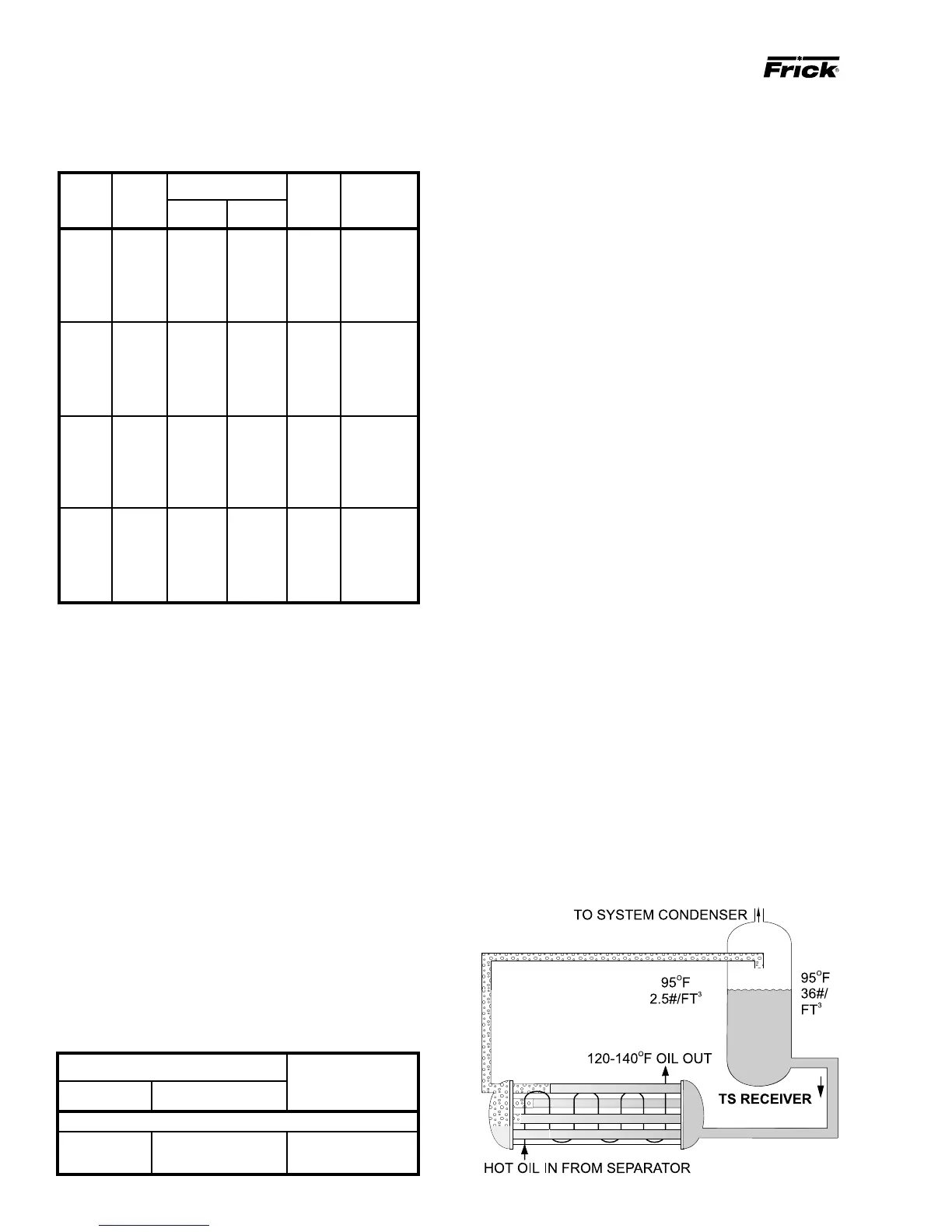
SYSTEM OPERATION - Liquid refrigerant fills the cooler
tube side up to the Thermosyphon receiver liquid level.
Water or hot oil (above the liquid temperature) flowing
through the cooler will cause some of the refrigerant to boil
and vaporize in the tubes. The vapor rises in the return line.
The density of the refrigerant liquid/vapor mixture in the re-
turn line is considerably less than the density of the liquid in
the supply line. This imbalance provides a differential pres-
sure that sustains a flow condition to the oil cooler. This re-
lationship involves:
1. Liquid height above the cooler.
2. Oil heat of rejection.
3. Cooler size and piping pressure drops.
INSTALLATION