RXB PLUS ROTARY SCREW COMPRESSOR UNITSS70-101 IOM
Page 14
INSTALLATION
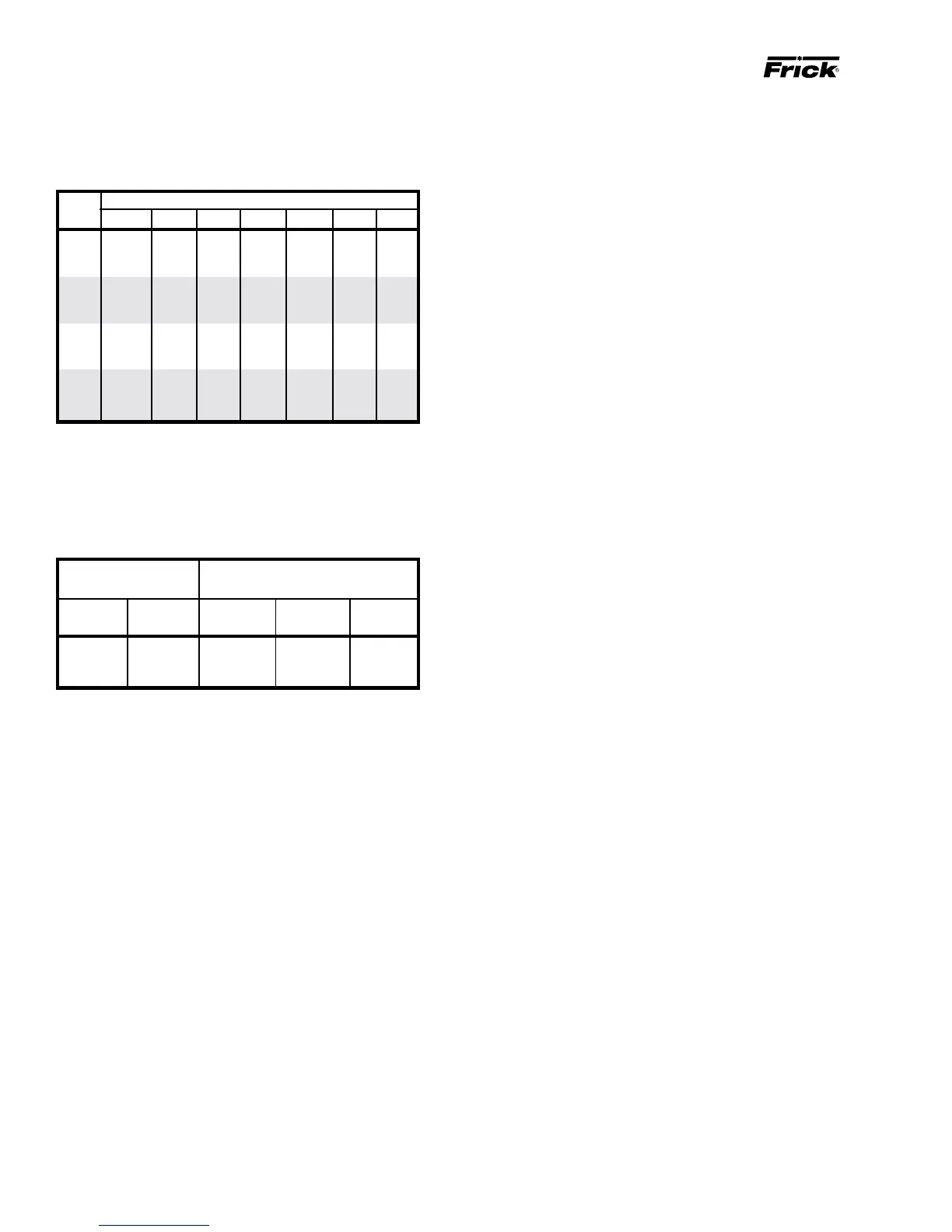
CURRENT TRANSFORMER (CT) RATIOS
The CT ratio for various motor sizes (with a 5 amp second-
ary) is given in the following table:
VOLTAGE
HP 200 230 380 460 575 2300 4160
20 100:5 100:5 100:5 100:5 100:5 - -
25 100:5 100:5 100:5 100:5 100:5 - -
30 200:5 100:5 100:5 100:5 100:5 - -
40 200:5 200:5 100:5 100:5 100:5 - -
50 200:5 200:5 100:5 100:5 100:5 - -
60 300:5 200:5 200:5 100:5 100:5 - -
75 300:5 300:5 200:5 200:5 100:5 - -
100 400:5 300:5 200:5 200:5 200:5 - -
125 500:5 400:5 300:5 200:5 200:5 - -
150 500:5 500:5 300:5 300:5 200:5 - -
200 800:5 600:5 400:5 300:5 300:5 100:5 50:5
250 800:5 800:5 500:5 400:5 300:5 100:5 50:5
MINIMUM BURDEN RATINGS
The following table gives the minimum CT burden ratings.
This is a function of the distance between the motor starting
package and the compressor unit.
BURDEN MAXIMUM DISTANCE FROM
RATING FRICK PANEL
USING # USING # USING #
ANSI VA 14 AWG 12 AWG 10 AWG
B-0.1 2.5 15 ft 25 ft 40 ft
B-0.2 5 35 ft 55 ft 88 ft
B-0.5 12.5 93 ft 148 ft 236 ft
In addition to the starter package interlocks shown on the
starter package diagram, the following optional interlocks
are on the typical RXB PLUS Screw Compressor unit with
the SBC Microprocessor Control System wiring diagram:
1. Remote LOAD, UNLOAD, and RUN interlocks in case the
customer desires to operate the unit from a remote control
device.
2. Alarm Horn output.
3. Control solenoid valve for the economizer option.
For customer control options, consult FRICK Company.
NOTE: The microprocessor will not operate without
EPROM chips installed. When EPROM chips are not in-
stalled, the microprocessor display will typically indi-
cate two dark lines across both the upper and lower dis-
play screens.
BATTERY BACKUP
The battery backup prevents data loss during power inter-
ruption. It will maintain the adjustable setpoints stored in
RAM (Random Access Memory) for up to 1 year after power
loss. Expected battery life is 10 years. A trickle charge main-
tains the battery backup at peak charge when control volt-
age is present.
To prevent power loss, the battery backup is shipped dis-
abled. To enable the battery backup, a jumper pin located
near the top of the microprocessor circuit board (see illus-
tration page 52) must be moved from OFF (pins 1-2) to ON
(pins 2-3).
NOTE: It is not necessary to disconnect the battery
backup during extended downtime.