RXB PLUS ROTARY SCREW COMPRESSOR UNITS S70-101 IOM
Page 13
ELECTRICAL
NOTE: Before proceeding with electrical installation, read
the instructions in the section “Proper Installation of
Electronic Equipment in an Industrial Environment”.
RXB PLUS units are supplied with a SBC (single-board com-
puter) microprocessor control system. Care must be taken
that the controls are not exposed to physical damage dur-
ing handling, storage, and installation. The microprocessor
enclosure cover must be kept tightly closed to prevent entry
of moisture and foreign matter.
Customer-control power connec-
tions are made at the BOTTOM of
the microprocessor enclosure.
Consult local ordinances before installation. Current
transformer wiring should be kept separate. Extreme
care should be taken that metal filings or other foreign
material is not left in the microprocessor enclosure. Use
seal-tight conduit fittings to prevent moisture entry into
the microprocessor enclosure. This is the ONLY electri-
cal enclosure that should be opened during installation
and it should be kept tightly closed whenever work is
not being performed in it.
1. The compressor motor starter of the specified HP and
voltage for the starting method specified (across-the-line,
autotransformer, wye-delta, or solid state).
NOTE: If starting methods other than across-the-line are
desired, a motor/compressor torque analysis must be
done to ensure that sufficient starting torque is avail-
able, particularly in booster applications. Contact FRICK
Company if assistance is required.
2. If specified, the starter package can be supplied as a
combination starter with circuit breaker disconnect. Howev-
er, the motor overcurrent protection/disconnection device
can be supplied by others, usually as a part of an electrical
power distribution board.
3. A 2.0 KVA control power transformer (CPT), to supply
120 volt control power to the control system and separator
oil heaters, is included. If environmental conditions require
more than a 500 watt oil heater, an appropriately oversized
control transformer will be required.
4. One (1) normally open, compressor-motor-starter auxil-
iary contact and 1 normally open, oil-pump-motor-starter
auxiliary contact (opt.) should be supplied and wired as
shown on the starter package wiring diagram. In addition,
the compressor and oil pump motor starter (opt.) coils and
the CPT secondaries should be wired as shown on starter
package wiring diagram.
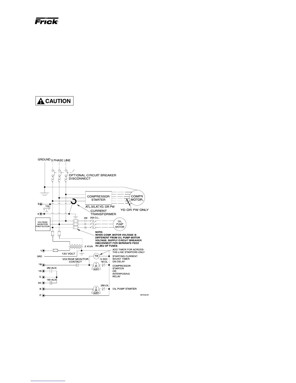
5. The compressor motor Current Transformer (CT) can be
installed on any one phase of the compressor leads. NOTE:
The CT must see all the current on any one phase; there-
fore in wye-delta applications, BOTH leads of any one
phase must pass through the CT.
6. Oil Pump Option: If the optional oil pump is specified, an
oil pump starter must be a component of the unit starter
package. The pump starter should be equipped with fuses
or, in the case where the compressor motor is a different
voltage from the oil pump motor, a circuit breaker discon-
nect suitable for separate power feed.
NOTE: Do not install a compressor HAND/OFF/AUTO
switch in the starter package as this would bypass the
compressor safety devices.
INSTALLATION
MOTOR STARTER PACKAGE
Motor starter and interlock wiring requirements are shown
in the wiring diagram, above. All the equipment shown is
supplied by the installer unless a starter package is pur-
chased from Frick . Starter packages should consist of:
NOTE: When compressor motor voltage is different from
oil pump motor voltage, supply a circuit breaker discon-
nect for separate feed in lieu of fuses.
NOTE: Customer ground required, see Micro Panel As-
sembly Wiring Diagram.