RXB PLUS ROTARY SCREW COMPRESSOR UNITS S70-101 IOM
Page 9
LIQUID INJECTION OIL COOLING
The liquid injection system provided on the unit is self-con-
tained but requires the connection of the liquid line sized as
shown in the table and careful insertion of the expansion
valve bulb into the thermowell provided in the separator. High
pressure gas is connected through the regulator to the ex-
ternal port on the liquid injection valve to control oil tem-
perature. Refer to the liquid injection piping diagram.
NOTE: For booster applications, the high pressure gas
connection must be taken from a high side source (high-
stage compressor discharge). This should be a minimum
3/8" line connected into the solenoid valve provided. This
gas is required by the expansion valve external port to
control oil temperature.
High-stage compressor units may be supplied with single-
port (low Vi) or dual-port (low Vi and high Vi), liquid injection
oil cooling. Single port will be furnished for low compression
ratio operation and dual port for high compression ratio op-
eration. Booster compressor units use single-port, liquid in-
jection oil cooling due to the typically lower compression
ratios.
The control system on high-stage units with dual-port, liq-
uid
injection oil cooling switches the liquid refrigerant supply to
the high port when the compressor is operating at higher
compression ratios (3.5 Vi and above) for best efficiency.
The following table gives the condensing temperature(s) with
the corresponding maximum evaporator temperature limit
for liquid injection usage and the minimum evaporator tem-
perature for a single-port application.
TABLE - EVAPORATOR TEMPERATURE with
SINGLE-PORT LIQUID INJECTION
MAXIMUM MINIMUM *
EVAPORATOR EVAP TEMP
CONDENS- TEMPERATURE FOR FOR
ING LIQUID INJECTION SINGLE PORT
TEMP USAGE (LOW Vi)
R-717 R-22 R-717 & R-22
75
O
F +10
O
F+5
O
F -23
O
F
85
O
F +25
O
F +15
O
F -17
O
F
95
O
F +35
O
F +25
O
F -11
O
F
105
O
F +40
O
F +35
O
F- 4
O
F
* Dual Injection Kit will be shipped by Frick
below these temperatures.
INSTALLATION
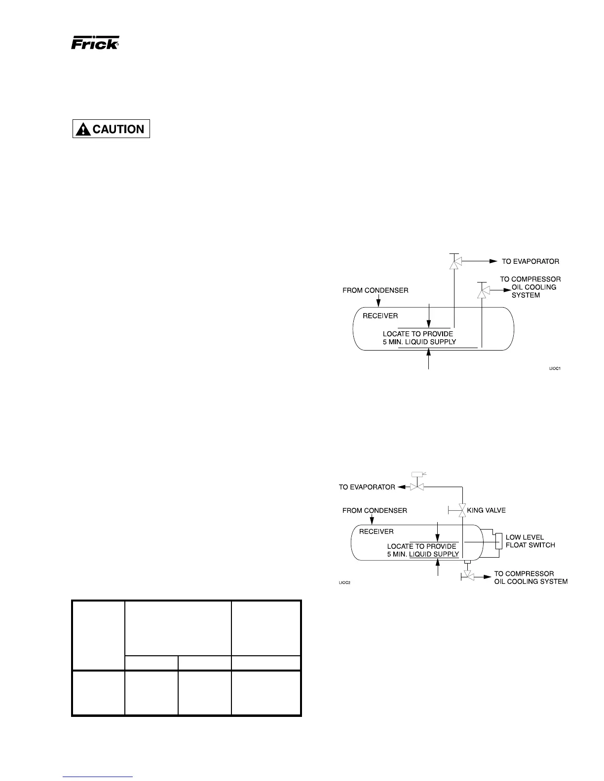
DUAL DIP TUBE METHOD
The dual dip tube method uses two dip tubes in the receiv-
er. The liquid injection tube is below the evaporator tube to
ensure continued oil cooling when the receiver level is low.
LEVEL CONTROL METHOD
The level control method utilizes a float level control on the
receiver to close a solenoid valve feeding the evaporator
when the liquid falls below that amount necessary for 5 min-
utes of liquid injection oil cooling.
start-up. Should additional heating capacity be required
because of unusual environmental condition, contact Frick
Company. The heater is energized only when the unit is not
in operation.
DO NOT ENERGIZE THE HEATER
WHEN THERE IS NO OIL IN THE
UNIT, OTHERWISE THE HEATER
WILL BURN OUT. THE OIL HEATER WILL BE ENERGIZED
WHENEVER 120 VOLT CONTROL POWER IS APPLIED
TO THE UNIT AND THE COMPRESSOR IS NOT RUNNING
UNLESS THE 10 AMP FUSE (1FU) IN THE CONTROL
PANEL IS REMOVED.
Where low compression ratios (low condensing pressures)
are anticipated, thermosyphon or water-cooled oil cooling
should be used. It is IMPERATIVE that an uninterrupted
supply of high pressure liquid refrigerant be provided to the
injection system at all times. Two items of EXTREME IM-
PORTANCE are the design of the receiver/liquid injection
supply and the size of the liquid line. It is recommended that
the receiver be oversized sufficiently to retain a 5 minute
supply of refrigerant for oil cooling. The evaporator supply
must be secondary to this consideration. Two methods of
accomplishing this are shown.