RXB PLUS ROTARY SCREW COMPRESSOR UNITS S70-101 IOM
Page 47
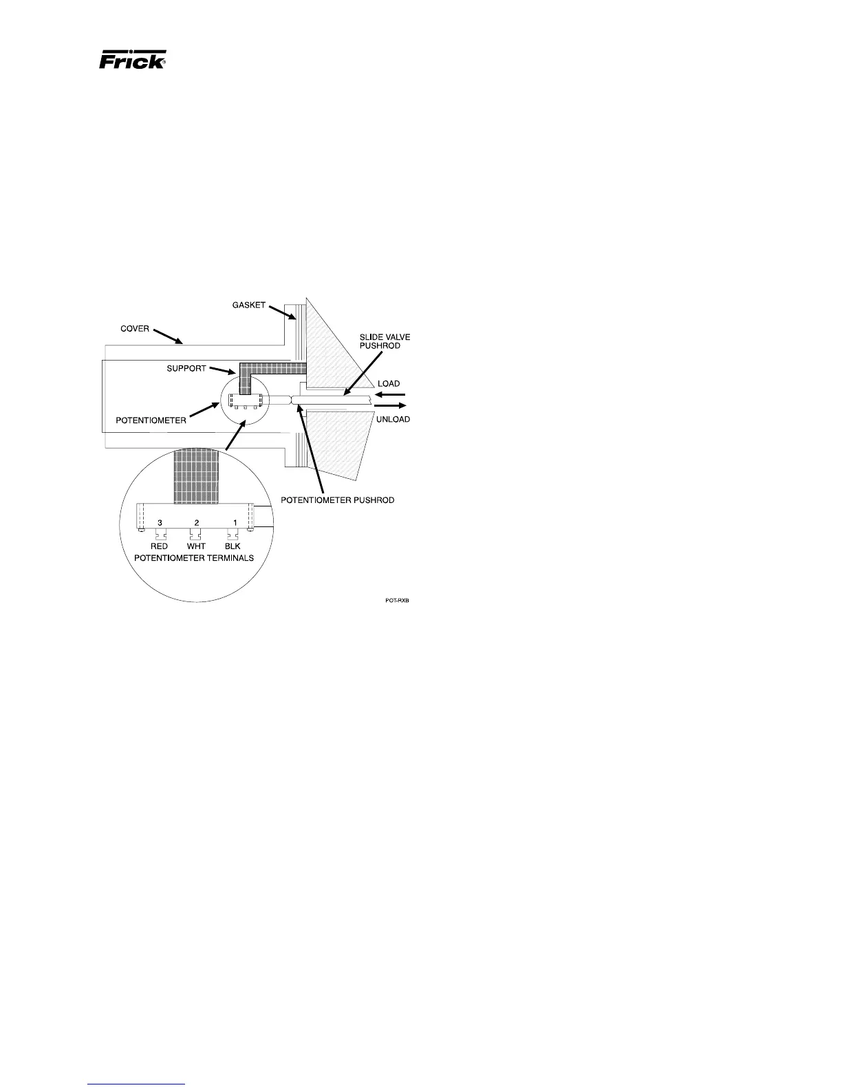
SLIDE VALVE POSITION POTENTIOMETER
REPLACEMENT AND ADJUSTMENT
The slide valve potentiometer is located under a cover on
the right side of the compressor (facing shaft) at the inlet
end.
1. Shut off control power.
2. Remove the potentiometer cover and gasket.
3. Remove the potentiometer and mounting bracket.
4. Install new potentiometer and bracket.
5. ADJUSTMENT must be made with the slide valve fully
unloaded and the compressor running. The Operating dis-
play at this time should indicate a slide valve position of 0%.
If the display is greater than 0%, adjust potentiometer POT
#4 on the SBC until 0% is indicated. If 0% is not attainable,
get as close as possible and then proceed to the next step.
The adjustments of POT #4 and POT #3 are interactive and
POT #3 may require adjustment to allow POT #4 to come
into range.
Completely load the slide valve at 2.2 Vi. The display at this
time should indicate 100%. If the display is less than 100%,
adjust potentiometer POT #3 on the SBC until 100% is indi-
cated.
Repeat this sequence until the slide valve indicates 0% fully
unloaded and 100% fully loaded.
TEMPERATURE and/or PRESSURE
ADJUSTMENT
All temperature and pressure sensors are factory set, cali-
bration is not required.
NOTE: Refer to page 22 for description on microproces-
sor offset adjustment for temperature and/or pressure.
MAINTENANCE
BARE COMPRESSOR MOUNTING
The following procedure is required only when a bare com-
pressor is replaced in the field.
1. Thoroughly clean the compressor feet and mounting pads
of burrs and other foreign matter to ensure firm seating of
the compressor.
2. Clean the discharge flange surfaces on the compressor
and separator.
3. Install a gasket on the compressor discharge connection
of the separator.
4. Set the compressor on its base and tighten the discharge
flange bolts. The feet of the compressor should lift off
the mounting base. If the compressor feet do not raise
off the mounting base install a thicker discharge gasket
and reinstall the discharge flange bolts. Check the clear-
ance between the feet and the base with a feeler gauge.
Shim the compressor feet (gauge reading plus .002").
5. Tighten compressor hold down bolts.
6. Complete compressor/motor coupling alignment (see IN-
STALLATION section).
7. Complete tubing, piping and wiring per the P & I and wir-
ing diagrams.