RXB PLUS ROTARY SCREW COMPRESSOR UNITSS70-101 IOM
Page 8
INSTALLATION
HOT ALIGNMENT OF COMPRESSOR/MOTOR
Hot alignments can only be made after the unit has oper-
ated for several hours and all components are at operating
temperatures.
Shut down the unit and quickly affix dial indicator to cou-
pling motor hub, then take readings of both the face and rim
of the compressor hub. If these readings are within toler-
ance, record reading, attach coupling guard, and restart unit.
However, if the reading is not within limits, compare the hot
reading with the cold alignment and adjust for this differ-
ence; i.e. if the rim at 0
O
and 180
O
readings indicates that
the motor rises .005" between its hot and cold state, .005"
of shims should be removed from under the motor.
After the initial hot alignment adjustment is made, restart
unit and bring to operating temperature. Shut down and re-
check hot alignment. Repeat procedure unit hot alignment
is within specified tolerance.
INSTALL COUPLING GUARD BE-
FORE OPERATING COMPRES-
SOR.
CHECKING MOTOR/COMPRESSOR
ROTATION
COMPRESSOR ROTATION IS CLOCKWISE WHEN FAC-
ING THE END OF THE COMPRESSOR SHAFT. Under NO
conditions should the motor rotation be checked with the
coupling center installed as damage to the compressor may
result.
HOLDING CHARGE AND STORAGE
Each compressor unit is pressure and leak tested at the
Frick factory and then thoroughly evacuated and charged
with dry nitrogen to ensure the integrity of the unit during
shipping and short term storage prior to installation.
NOTE: Care must be taken when entering the unit to
ensure that the nitrogen charge is safely released.
All units must be kept in a clean, dry location to prevent
corrosion damage. Reasonable consideration must be given
to proper care for the solid state components of the micro-
processor. Unit which will be stored for more than two
months must have the nitrogen charge checked peri-
odically.
COMPRESSOR
COMPRESSOR UNIT OIL
DO NOT MIX OILS of different
brands, manufacturers, or types.
Mixing of oils may cause excessive
oil foaming, nuisance oil level cutouts, oil pressure loss,
gas or oil leakage and catastrophic compressor failure.
Use of oils other than Frick Oil must
be approved in writing by Frick en-
gineering or warranty claim may be
denied.
Use of filter elements other than
Frick must be approved in writing
by Frick engineering or warranty
claim may be denied.
The oil charge shipped with the unit is the best suited lubri-
cant for the conditions specified at the time of purchase. If
there is any doubt due to the refrigerant, operating pres-
sures, or temperatures; refer to Frick Pub. E160-802 SPC
for guidance.
OIL CHARGE
The normal charging level is midway in the top sight glass
located midway along the oil separator shell. Normal oper-
ating level is between the top sight glass and bottom sight
glass. The following table gives the approximate oil charge
quantity.
TABLE - BASIC OIL CHARGE (Gal)
MODEL BASIC CHARGE* (GAL.)
12 10
15 10
19 14
24 14
30 17
39 17
50 21
* Add oil volume for external oil cooler, according to cooler
size selected: 6 x 5 TSOC - 4 gal.; 6 x 5 WCOC - 5 gal.; 8 x
5 TSOC - 6-1/2 gal.; and 8 x 5 WCOC - 8 gal.
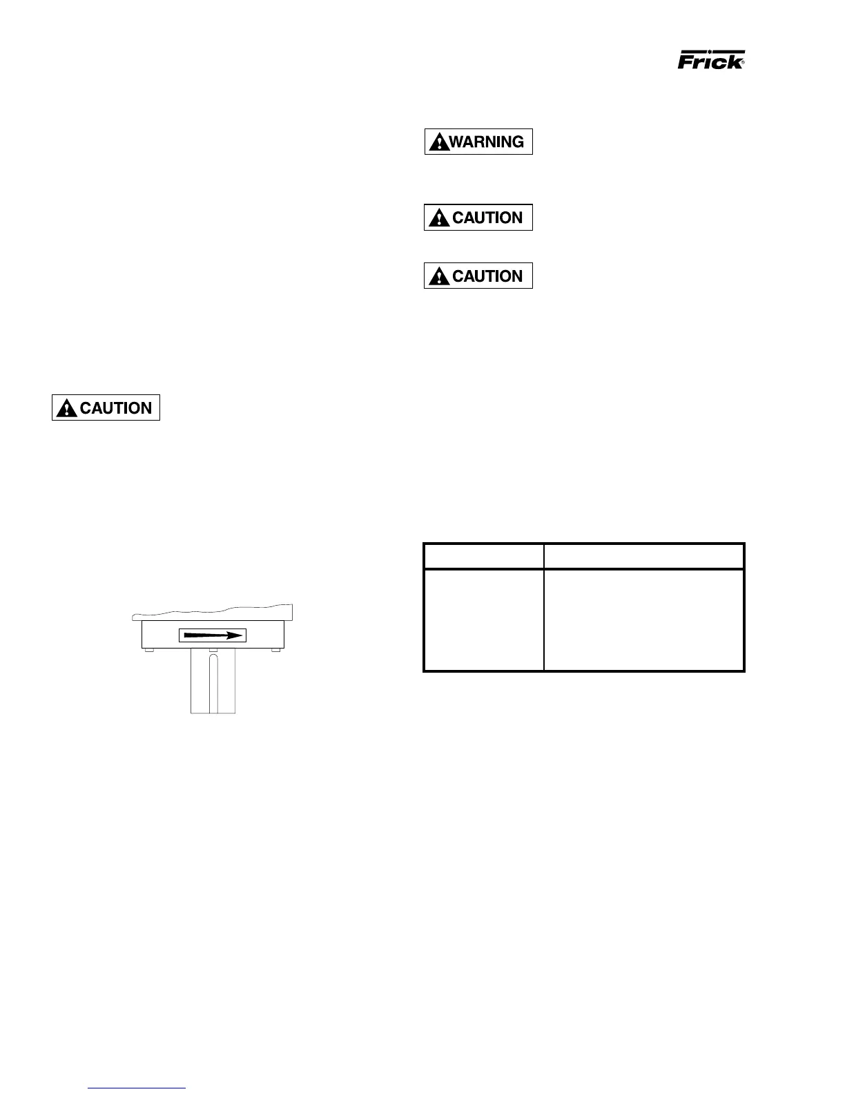
Add oil by attaching the end of a suitable pressure type
hose to the oil charging valve, located on the top of the oil
separator on the compressor end of the separator. Using a
pressure-type pump and the recommended Frick oil, open
the charging valve and pump oil into the separator.
Oil distillers and similar equipment which act to trap oil must
be filled prior to unit operation to normal design outlet lev-
els. The same pump used to charge the unit may be used
for filling these auxiliary oil reservoirs.
NOTE: The sight glass, located near the bottom of the
separator shell at the discharge end, should remain
empty when the unit is in operation. The presence of oil
in this end of the vessel during operation indicates liq-
uid carryover or malfunction of the oil return.
OIL HEATER
Standard units are equipped with a 500 watt oil heater, pro-
viding sufficient heat to maintain the oil temperature for most
indoor applications during shutdown cycles to permit safe