RXB PLUS ROTARY SCREW COMPRESSOR UNITS S70-101 IOM
Page 15
OPERATION and START-UP INSTRUCTIONS
GENERAL INFORMATION
The Frick RXB PLUS Rotary Screw Compressor Unit is an
integrated system consisting of six major subsystems:
1. Microprocessor Control Panel
2. Compressor
3. Compressor Lubrication System
4. Compressor Oil Separation System
5. Compressor Hydraulic System
6. Compressor Oil Cooling System
The information in this section of the manual provides the
logical step-by-step instructions to properly start up and op-
erate the RXB PLUS Rotary Screw Compressor Unit.
THE FOLLOWING SUBSECTIONS MUST BE READ AND
UNDERSTOOD BEFORE ATTEMPTING TO START OR
OPERATE THE UNIT.
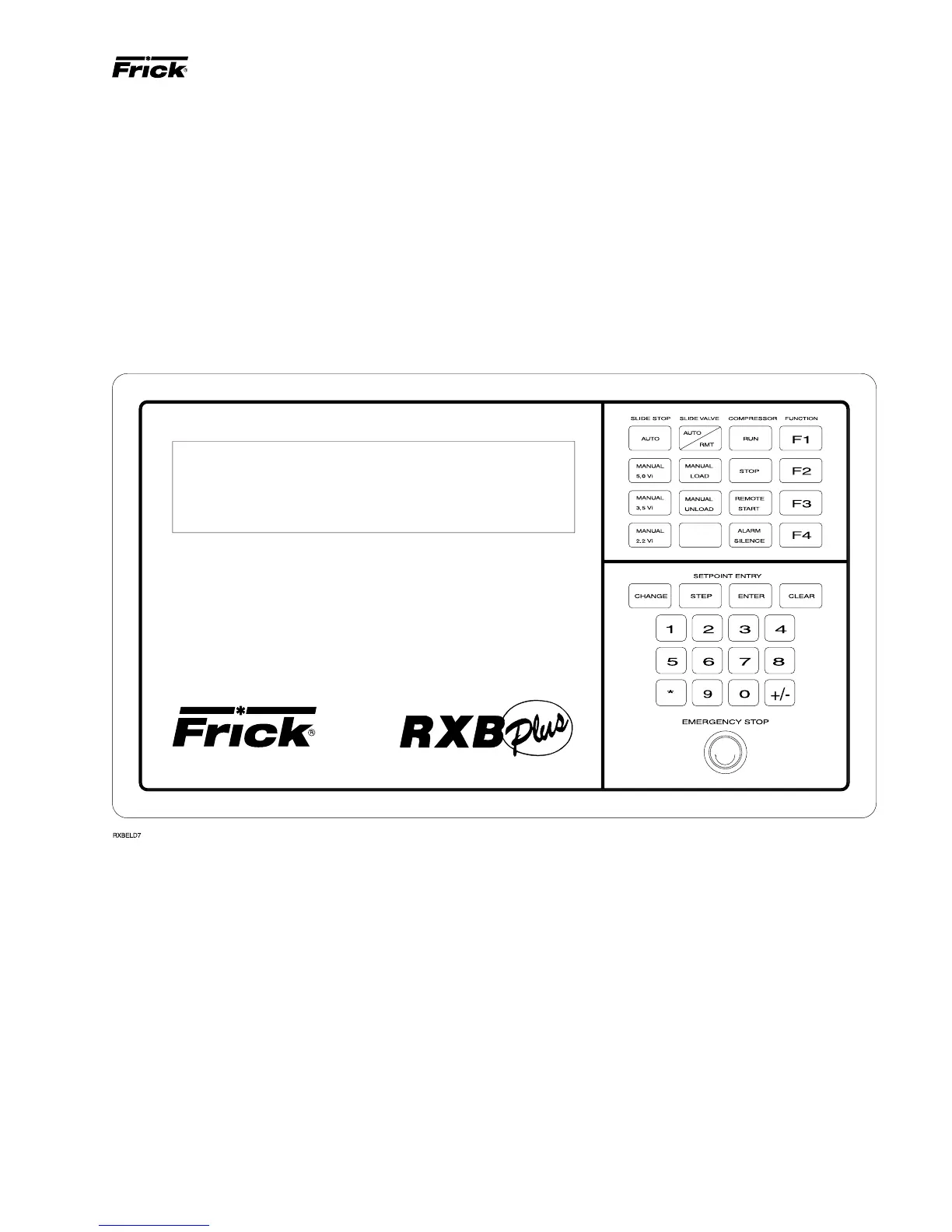
MICROPROCESSOR CONTROL PANEL
The RXB PLUS compressor is controlled by a state-of-
the-art microprocessor control system. The microprocessor
continuously monitors the compressor unit’s condition and
operation. The microprocessor also directs instructions to
the various compressor unit subsystems.
The microprocessor has a membrane switch keyboard.
Pressing the keyboard in the area outlined as a key will cause
that function to be recognized by the microprocessor. The
keyboard has 32 membrane-type keys.
In addition to the keyboard, there is an emergency stop but-
ton. Pushing the emergency stop will bypass the computer
and remove all power from the outputs. This will shut down
the compressor motor and all high voltage to the compres-
sor auxiliary systems such as the oil pump and liquid injec-
tion solenoid. THE EMERGENCY STOP BUTTON IS FOR
EMERGENCY SHUTDOWN SITUATIONS ONLY and
MUST NOT BE USED TO ROUTINELY SHUT OFF THE
COMPRESSOR.
The microprocessor continuously monitors the state of the
battery which maintains setpoints and various other data. If
the battery voltage is low, the message “LOW BATT” will
flash in the lower right hand corner of the bottom display
(see page 14 for description of battery backup).
The microprocessor hardware contains an output watch-
dog circuit. If the microprocessor should fail, this circuit will
disable (turn off) all outputs.
OPERATION