RXB PLUS ROTARY SCREW COMPRESSOR UNITS S70-101 IOM
Page 31
OPERATION
COMPRESSOR HYDRAULIC SYSTEM
The compressor hydraulic system moves the movable slide
valve (MSV) to load and unload the compressor. It also
moves the movable slide stop (MSS) to increase or decrease
the compressor’s volume ratio (Vi).
CAPACITY CONTROL
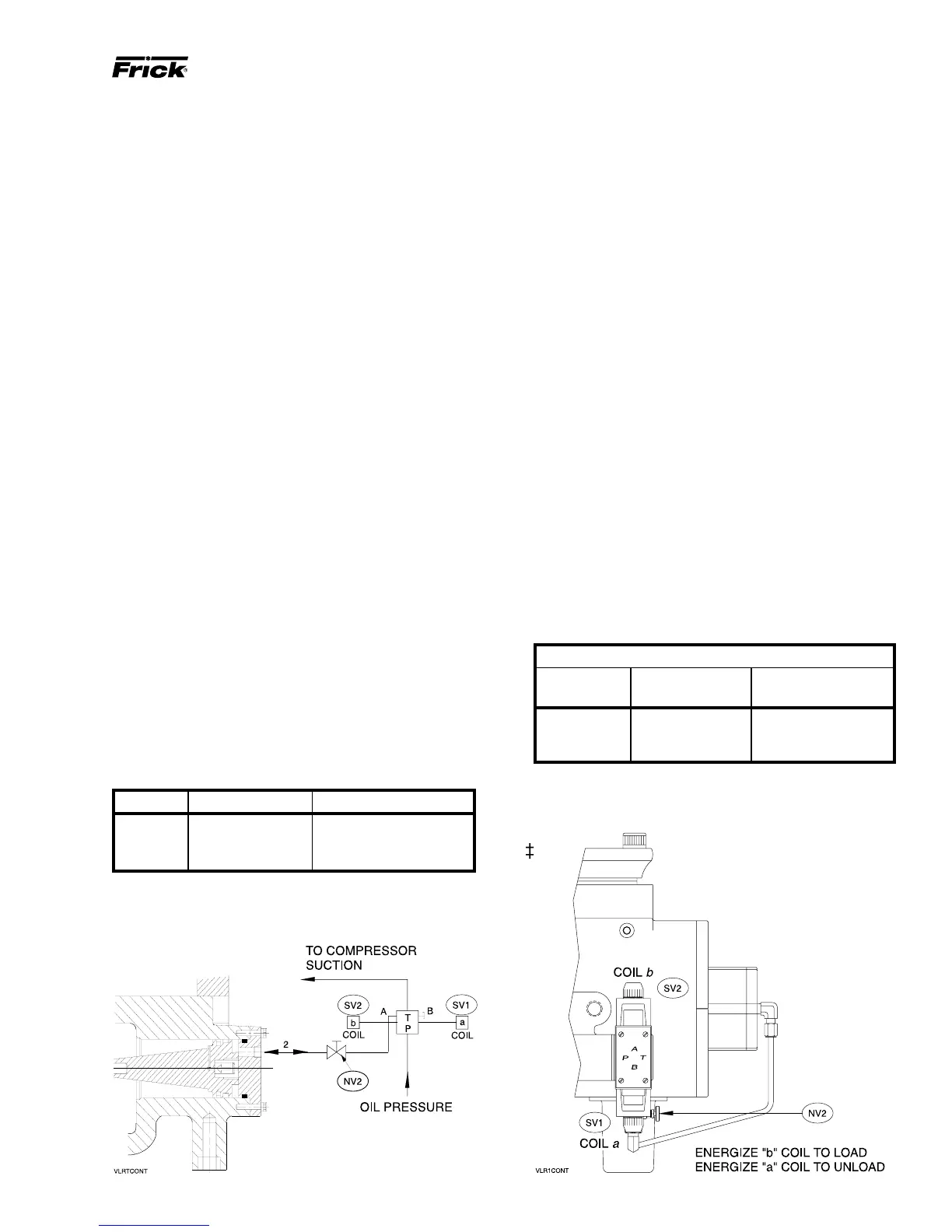
COMPRESSOR LOADING: If the capacity control valve is
mounted on the base, the compressor loads when MSV so-
lenoid coil SV1 is energized. If the capacity control valve is
mounted on the compressor, the compressor loads when
MSV solenoid coil SV2 is energized. Oil flows from the sole-
noid valve through the needle valve (NV2) to compressor
port 2, where it enters the load side of the slide valve piston.
This equalizes the force on the slide valve piston and dis-
charge pressure on the slide valve area loads the compressor.
COMPRESSOR UNLOADING: If the capacity control valve
is mounted on the base, the compressor unloads when MSV
solenoid SV2 is energized. If the capacity control valve is
mounted on the compressor, the compressor unloads when
MSV solenoid coil SV2 is energized. Oil is allowed to flow
from compressor port 2 through the needle valve to the MSV
solenoid. This allows discharge pressure on the slide valve
piston to unload the slide valve as the piston moves outward.
ADJUSTMENT (Capacity Control): A needle valve (NV2)
is provided to adjust slide valve travel time, preventing ex-
cessive slide valve “hunting”. NV2 should be adjusted to
restrict oil flow to compressor port so that slide valve travel
time from full load to full unload, or vice versa is a minimum
of 30 seconds.
NOTE: A change in operating conditions may require
readjustment of Slide Valve travel time (NV).
VOLUMIZER
®
II Vi CONTROL
Solenoid valves 3 and 4 control the Vi Ratio. Oil is internally
ported to move the Movable Slide Stop.
Vi SOL-3 (TOP) SOL-4 (BOTTOM)
2.2 Energized Energized
3.5 De-energized Energized
5.0 De-energized De-energized
CAPACITY CONTROL VALVE MOUNTED ON BASE
FUNCTIONAL CHECK OF THE COMPRESSOR
VOLUME RATIO CONTROL (Vi) OPERATION
1. Remove the slide valve potentiometer cover located on
the outlet end of the compressor and secured by 4 cap
screws.
2. Push the Slide Stop Manual 2.2 Vi key on the micro keypad.
3. Push Manual Load on the Slide Valve Control and hold in
the depressed position until the compressor is fully loaded.
4. Remove the Capacity Position Potentiometer which is
secured by 2 bolts. This will expose the indicator rod which
protrudes from the indicator rod guide.
5. In the 2.2 Vi position, the rod should extend from the
guide the amount shown in the Indicator Rod Extension
table.
6. With the slide valve fully loaded, depress the manual 3.5
Vi key. Movement of the indicator rod should occur as the
Vi is changed so that the rod extension corresponds to the
table.
7. Reassemble the parts if the functional check is satisfac-
tory.
If the indicator rod does not move to the proper position as
the table indicates, then the compressor is not changing Vi
in either manual or optional automatic operation. This would
result in higher compressor motor horsepower consump-
tion and possibly high oil temperature. The problem would
be caused by a malfunction of either solenoid valve 3SOL
or 4SOL, or the solenoid coil. Replace as required.
INDICATOR ROD EXTENSION (in.)
Vi RXB RXB
POSITION 12, 15, & 19 24, 30, 39, & 50
2.2 .412 / .454 .434 / .474
3.5 .297 / .339 .319 / .359
5.0 .235 / .277 .258 / .298
CAPACITY CONTROL VALVE ON COMPRESSOR