RXB PLUS ROTARY SCREW COMPRESSOR UNITS S70-101 IOM
Page 5
INSTALLATION
MAXIMUM
TOTAL
INDICATOR
READING
CLAMP
BOLT
TORQUE
KEYWAY
SETSCREW
TORQUE
BETWEEN SHAFT SPACING
SHAFT ENGAGEMENT
FACE SPACING
CH
COUP-
LING
SIZE in. mm mm mmin. in. mm in. in. mm in. mm ft-lb Nm ft-lb Nm
COUPLING HUB
MIN *
MAX
MIN MAX
CH COUPLING DATA TABLE
76.2
76.2
96.8
90.5
101.6
138.1
161.9
149.2
23.8
34.9
46.0
60.3
19.0
25.4
25.4
31.8
22.2
27.0
28.6
36.5
3
3
3-13/16
3-9/16
3/4
1
1
1-1/4
15/16
1-3/8
1-13/16
2-3/8
7/8
1-1/16
1-1/8
1-7/16
.004
.004
.004
.004
.104
.104
.104
.104
10
20
35
35
13.6
27.1
47.5
47.5
13
13
13
13
17.6
17.6
17.6
17.6
3-1/4
3-7/16
4
5-7/16
6
7
8
9C
FIG. 2 - ALTERNATIVE LIFTING METHOD
The unit can be moved with a forklift by forking under the
skid, or it can be skidded into place with pinch bars by push-
ing against the skid. NEVER MOVE THE UNIT BY PUSH-
ING OR FORKING AGAINST THE SEPARATOR SHELL
OR ITS MOUNTING SUPPORTS.
SKID REMOVAL
If the unit is rigged into place the skid can be removed by
taking off the nuts and bolts that are fastening the unit mount-
ing supports to the skid before lowering the unit onto the
mounting surface.
If the unit is skidded into place, remove the cross members
from the skid and remove the nuts anchoring the unit to the
skid. Using a 5-ton jack under the separator, raise the unit at
the compressor end until it clears the two mounting bolts.
Spread the skid to clear the unit mounting support, then lower
the unit to the surface. Repeat procedure on opposite end.
MOTOR MOUNTING
The following procedure is required only when the motor is
mounted at the job site.
1. Thoroughly clean the motor feet and mounting pads of
grease, burrs, and other foreign matter to ensure firm seat-
ing of the motor.
2. Attach the motor to the base using the bolts and motor-
raising blocks, if required. Bolt snugly through the base.
3. Weld the four kick bolts into place so that they are posi-
tioned to allow movement of the motor feet.
4. Now that the motor has been set, check that the shafts
are properly spaced for the coupling being used. Refer to
the coupling data table for the applicable dimension.
COMPRESSOR/MOTOR COUPLING
INSTALLATION
RXB PLUS units are arranged for direct motor drive and
require a flexible drive coupling to connect the compressor
to the motor. Before installing, perform the following:
1. Inspect the shaft of the motor and compressor to ensure
that no nicks, grease, or foreign matter is present.
2. Inspect the bores in the coupling hubs to make sure that
they are free of burrs, dirt, and grit.
3. Check that the keys fit the hubs and shafts properly.
CH COUPLING – The T.B. Woods Elastomeric CH Coupling
is used in most applications. It consists of two drive hubs
and a loose, gear-type Hytrel Drive Spacer. The split hub is
clamped to the shaft by tightening the clamp screws. Torque
is transmitted from the motor through the elastomeric gear
which floats freely between the hubs. Install as follows:
IT IS MANDATORY THAT THE COU-
PLING CENTER BE REMOVED
AND THE DIRECTION OF MOTOR
ROTATION BE CONFIRMED
BEFORE
RUNNING THE
COMPRESSOR. Proper rotation of the compressor shaft
is clockwise looking at the end of the compressor shaft.
FAILURE TO FOLLOW THIS STEP COULD RESULT IN
BACKWARD COMPRESSOR ROTATION WHICH CAN
CAUSE COMPRESSOR FAILURE OR EXPLOSION OF
THE SUCTION HOUSING.
1. Slide one hub onto each shaft as far as possible. It may
be necessary to use a screwdriver as a wedge in the slot to
open the bore before the hubs will slide onto the shafts.
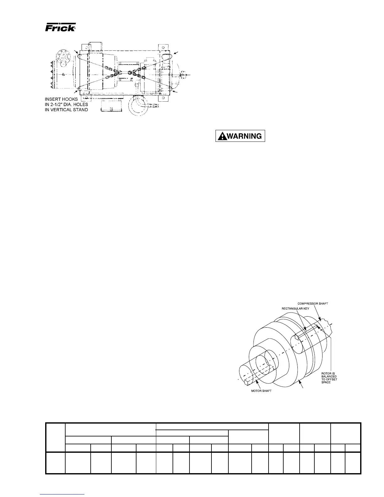
2. Hold the elastomeric gear between the hubs and slide
both hubs onto the gear to fully engage the mating teeth.
Make sure that the keys on the compressor and motor halves
of the coupling are offset 180
O
(see FIG. 3). Center the gear
and hub assembly so there is equal engagement on both
shafts. Adjust the space between hubs as specified in the
CH Coupling Data Table below.
3. Torque the clamping bolts in both hubs to the torque value
given in the CH Data Table. DO NOT USE ANY LUBRI-
CANT ON THESE BOLTS.
4. Proceed to Coupling Alignment.
DRIVE COUPLING
FIG. 3 - COUPLING/SHAFT KEYS INSTALLATION