RXB PLUS ROTARY SCREW COMPRESSOR UNITSS70-101 IOM
Page 12
INSTALLATION
ECONOMIZER - HIGH STAGE (OPTIONAL)
The economizer option provides an increase in system ca-
pacity and efficiency by subcooling liquid from the condenser
through a heat exchanger or flash tank before it goes to the
evaporator. The subcooling is provided by flashing liquid in
the economizer cooler to an intermediate pressure level.The
intermediate pressure is provided by a port located part way
down the compression process on the screw compressor.
As the screw compressor unloads, the economizer port will
drop in pressure level, eventually being fully open to suc-
tion. Because of this, an output from the microprocessor is
generally used to turn off the supply of flashing liquid on a
shell and coil or DX economizer when the capacity falls be-
low approximately 45%-60% capacity (85%-90% slide valve
position). This is done because the compressor will be more
efficient operating at a higher slide valve position with the
economizer turned off, than it will at a low slide valve posi-
tion with the economizer turned on. Please note however
that shell and coil and DX economizers can be used at low
compressor capacities in cases where efficiency is not as
important as ensuring that the liquid supply is subcooled. In
such cases, the economizer liquid solenoid can be pro-
grammed to be left open whenever the compressor is run-
ning.
Due to the tendency of the port pressure to fall with de-
creasing compressor capacity, a back-pressure regulator
valve (BPR) is generally required on a flash economizer
system (FIG. 3) in order to maintain some preset pressure
difference between the subcooled liquid in the flash vessel
and the evaporators. If the back-pressure regulator valve is
not used on a flash economizer, it is possible that no pres-
sure difference will exist to drive liquid from the flash vessel
to the evaporators, since the flash vessel will be at suction
pressure. In cases where wide swings in pressure are an-
ticipated in the flash economizer vessel, it may be neces-
sary to add an outlet pressure regulator to the flash vessel
outlet to avoid overpressurizing the economizer port, which
could result in motor overload. Example: A system feeding
liquid to the flash vessel in batches.
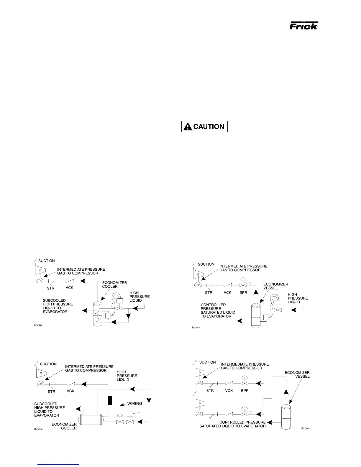
The recommended economizer systems are shown below.
Notice that in all systems there should be a strainer (STR)
and a check valve (VCK) between the economizer vessel
and the economizer port on the compressor. The strainer
prevents dirt from passing into the compressor and the check
valve prevents oil from flowing from the compressor unit to
the economizer vessel during shutdown.
Other than the isolation valve
needed for strainer cleaning, it is
essential that the strainer be the
last device in the economizer line before the compres-
sor. Also, piston-type check valves are recommended
for installation in the economizer line, as opposed to
disc-type check valves. The latter are more prone to gas-
pulsation-induced failure. The isolation and check val-
ves and strainer should be located as closely as pos-
sible to the compressor, preferably within a few feet.
For refrigeration plants employing multiple compressors on
a common economizing vessel, regardless of economizer
type, each compressor must have a back-pressure regulat-
ing valve in order to balance the economizer load, or gas
flow, between compressors. The problem of balancing load
becomes most important when one or more compressors
run at partial load, exposing the economizer port to suction
pressure. In the case of a flash vessel, there is no need for
the redundancy of a back-pressure regulating valve on the
vessel and each of the multiple compressors. Omit the BPR
valve on the flash economizer vessel and use one on each
compressor, as shown in FIG. 4.
FIG. 2 - DIRECT EXPANSION ECONOMIZER SYSTEM
FIG. 1 - SHELL and COIL ECONOMIZER SYSTEM
FIG. 4 -MULTIPLE COMPRESSOR ECONOMIZER SYSTEM
FIG. 3- FLASH ECONOMIZER SYSTEM