J. Replace the cover as outlined in section 4.2.2.
K. Place the unit inside the simulated garden, as explained in section 5.1 and turn the Perimeter
Switch on.
L. Perform ‘Factory defaults’ under the ‘Service’>’Settings’ menu (section 5.5.6)
M. Perform the following under the ‘Service’>’Calibration’ menu:
i. ‘Learn wire sensors’ (section 5.3.1)
ii. ‘Edge Calibration’ (section 5.3.2)
iii. ‘Set country’ (section 5.3.3)
iv. ‘D.K Calibration’ (section 5.3.4)
N. Complete the General Test as outlined in section 5.1.
4.2.4 Other Board Replacement
4.2.4.1 Connector Board Replacement
Required tools: Wide flat screwdriver Procedure duration: 5 minutes
A. Remove the Power Pack from the Robomow.
B. Remove the cover, as outlined in section 4.2.1.
C. Remove the flat cable by pulling the two lever arms outwards.
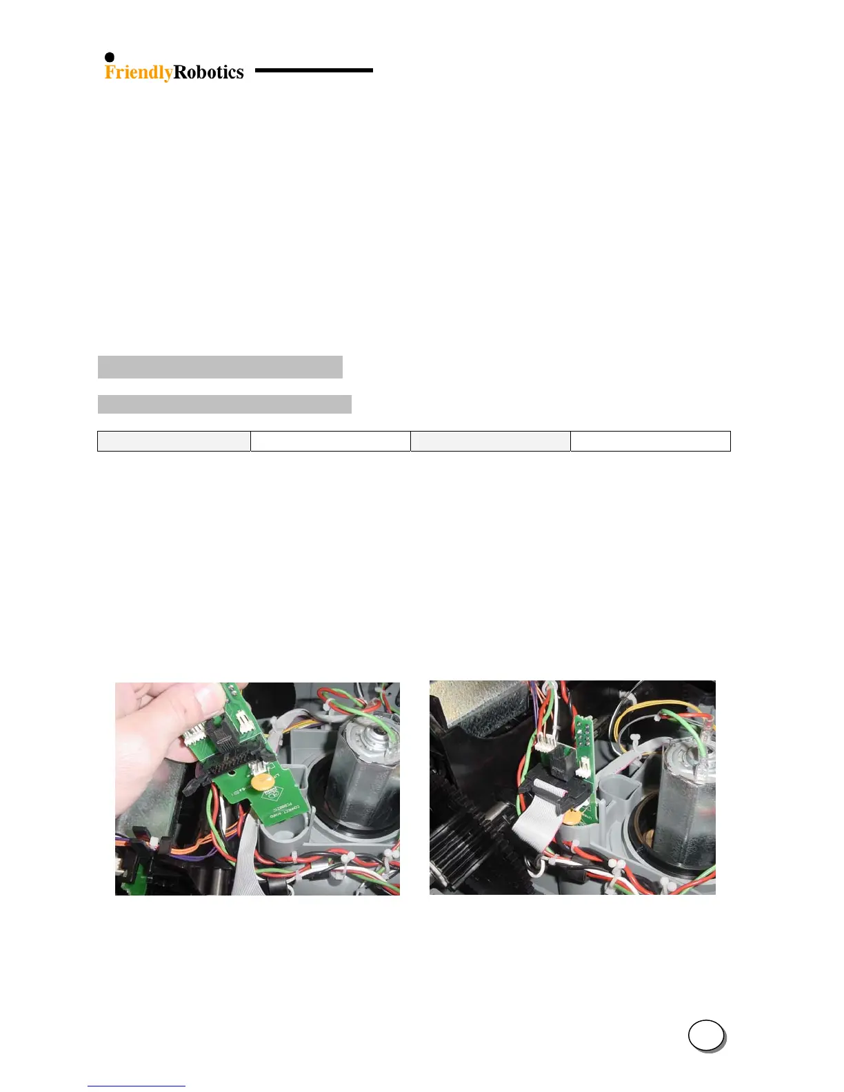
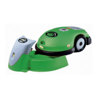
D. Slide the Connector Board upwards to remove, as illustrated in Figure 4.2.4.1.1 below.
E. Take the new Connector Board and insert it into its positioning slots. Make sure it fits all the
way into the slots.
F. Make sure both lever arms of the flat cable socket are extended outside. Take the flat cable
connector and place it against the socket on the Connector Board. Make sure the protrusion on
the connector is against the notch in the socket. Press the connector into place and both lever
arms will close on the connector, as illustrated in Figure 4.2.4.1.2 below.
Figure 4.2.4.1 Figure 4.2.4.2
Connectors board replacement Connector Board in its proper position
G. Close the cover, as outlined in section 4.2.
H. Complete the General Test as outlined in section 5.1.
4
18