3
3.2.2 Power & Charging Problems
11
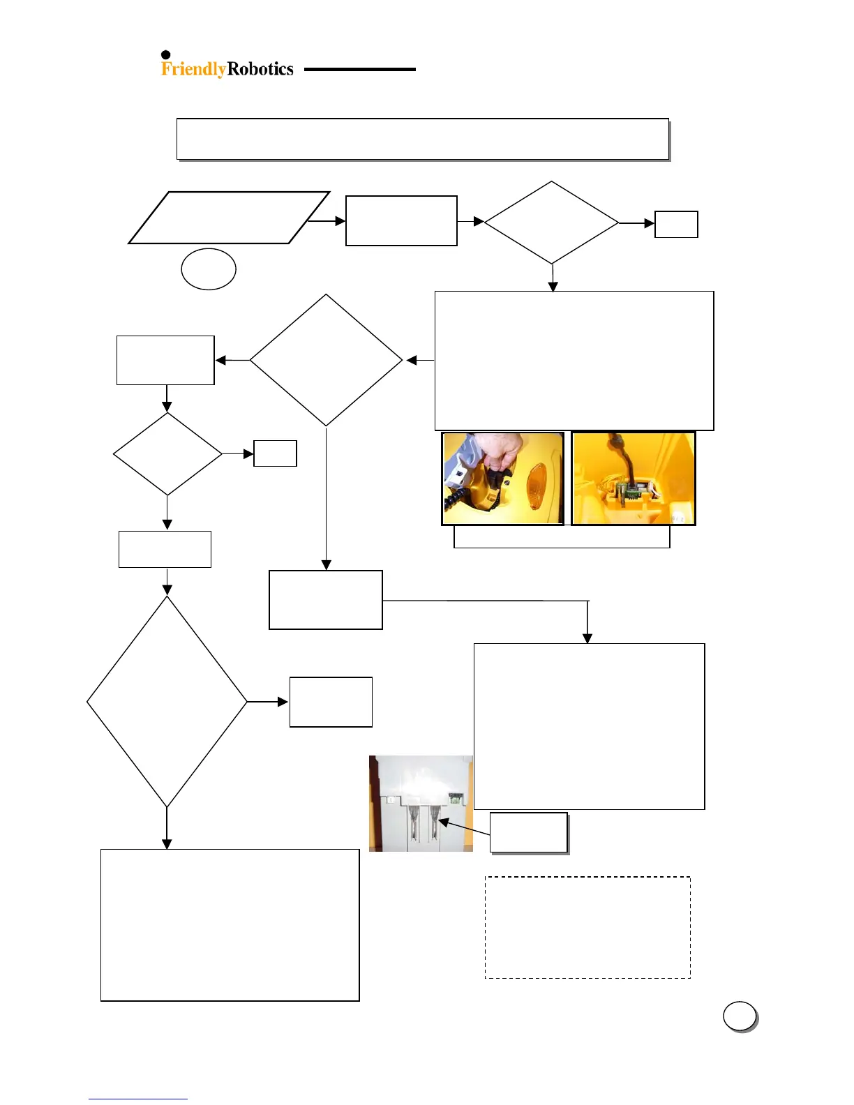
Remove Top
Cover
NO
Confirm the user properly maintains
battery by checking the parameters
under ‘Battery maintenance’ menu (The
‘Last Bat. Volt’ parameter indicates the
last measured voltage of the battery –
it can show if the battery was charged
at the end of the last operation)
ES
Confirm battery contacts on both sides (Bat. and
Robomower) are not loose/damaged
Check battery fuse (30A) is not blown (located in
battery case)
Check main fuse (1A) and charging fuse (5A) are not
loose/blown/rusty (located on connector board (in
manual controller pocket under black/gray cover)
Confirm good contact between m. controller cable
plug and socket on the connector board
Open the power pack cover and check connections
The Power Pack must have at least 14 volts
for the Robomower to wake up. Connecting
a standard 12 volt, 1-3 amp automotive type
charger to the connectors on the outside of
the power pack and charging for 12 hours
will usually bring the voltage up to 14 volts,
enough to wake up the mower. If so, allow
the mower to fully charge the power pack
on-board as normal. If it does not succeed,
replace the power pack.
(The positive+ connector on the power pack
is the connector closest to the 30-amp fuse).
Does not ‘wake up’
when ‘GO’ is
pressed
3.2.2.1
onents?
Replace Connector Board
Replace Connector cable
Replace main board and follow the instructions
attached to the spare part board (Service
Bulletin) – use the most updated S/W version
flash and complete the following settings (under
the ‘Service’ menu):
o ‘Learn wire sensors’ (Refer to chapter 5.3.3)
o ‘Edge Calibration (Refer to chapter 5.3.2)
o ‘Set country’
o ‘DK Calibration’ (Refer to chapter 5.3.1)