H. Verify that both gray plastic retaining clips are back in place and are holding the wire sensor
holder, as illustrated in Figure 4.2.7.5.
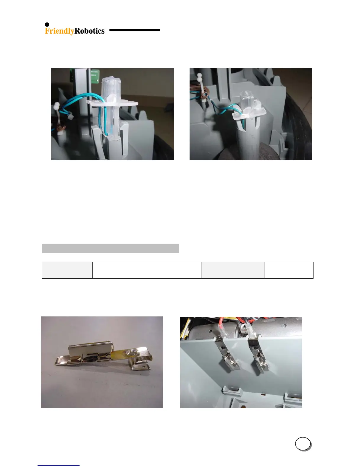
Figure 4.2.7.4 Figure 4.2.7.5
Proper direction to place wire sensor holder Proper position of wire sensor holder in its place
I. Return the cover as outlined in section 4.2.2.
J. Perform ‘Learn wire sensors’ (see section 5.3.1)
K. Perform ‘Edge calibration’ (see section 5.3.2)
L. Perform ‘Wire sensors test, as outlined in’ section 5.4.1.
M. Complete the General Test as outlined in section 5.1.
4.2.8 Power Pack contacts replacement
Required tools: Wide flat screwdriver
Tapered pliers
Procedure duration: 5 minutes
The Power Pack contact is made of 2 parts, as seen in Figure 4.2.8.1 below.
This design is made only for production purposes. The spare part and the replacement procedure
are for replacing the 2 parts assembled.
Figure 4.2.8.1 Figure 4.2.8.2
Power Pack contact assembly Power Pack contacts
4
34