3
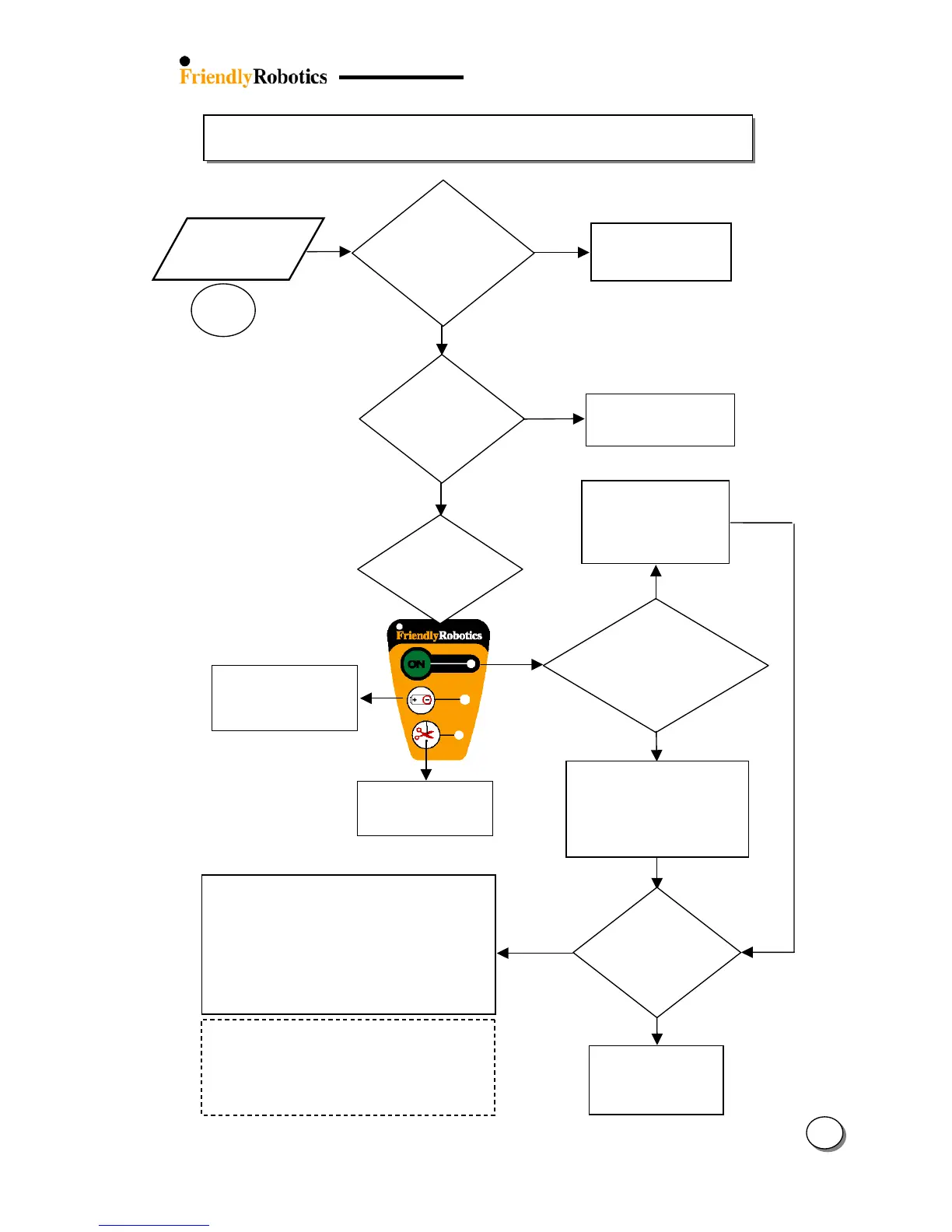
3.2.10 Wire Sensors Problems
31
3.2.10.1
ES
Is the
Perimeter
Switch/Dockin
urn on the Perimeter
Switch by pressin
the
‘on’ button
NO
Move the Robomow
towards the wire and
press the GO again
(Min. signal is needed
to start the operation)
ES
NO
Refer to flowchart 3.1.3
– ‘Perimeter Switch
Refer to flowchart 3.1.2
- Replace batteries –
only for standard
Which LED on
the P. Switch
blinking?
Refer to flowchart
5.3.1 - Wire
Disconnected
Has the message
been received
durin
operation or
upon GO pressing?
During
operation
Upon
pressing GO
Confirm the plot is not too bi
(Robomower’s distance from
the nearest perimeter wire
should be less than 50ft/15m
when the wire sensors readin
est the wire
sensors
readings
(see
section 5.4.1)
Pass
Fail
Look for double
wires, separate the
wires and confirm
the readings are OK
Too tightly pegged double wires can cause short
and reduce wire sensors readings.
Double wires can be found between:
Perimeter wire and Perimeter Islands
Perimeter Wire and Perimeter Switch
lots
Refer to fault code (see table 5.6)
Replace Wire Sensors (SPP0018A)
Replace Main Board (SPP0019B) and complete
the following settings (under the ‘Service’ menu):
- ‘Factory default’ (Section 5.5.6)
- ‘Learn wire sensors’ (Section 5.3.1)
- ‘Edge Calibration (Section 5.3.2)
- ‘Set country’ (Section 5.3.3)
- ‘DK Calibration’ (Section 5.3.4)
Is any LED
blinking on
the Perimeter
Switch?