3.3 Assembly work
3.3.1 Installing the chamber in the boiler
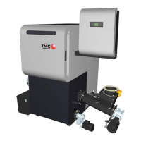
If the boiler has been placed in the right position, 4 rubber supports
must be inserted beneath the bottom of the boiler:
U Lift boiler
U Place 4 rubber supports on the 4 corners of the bottom of the boiler
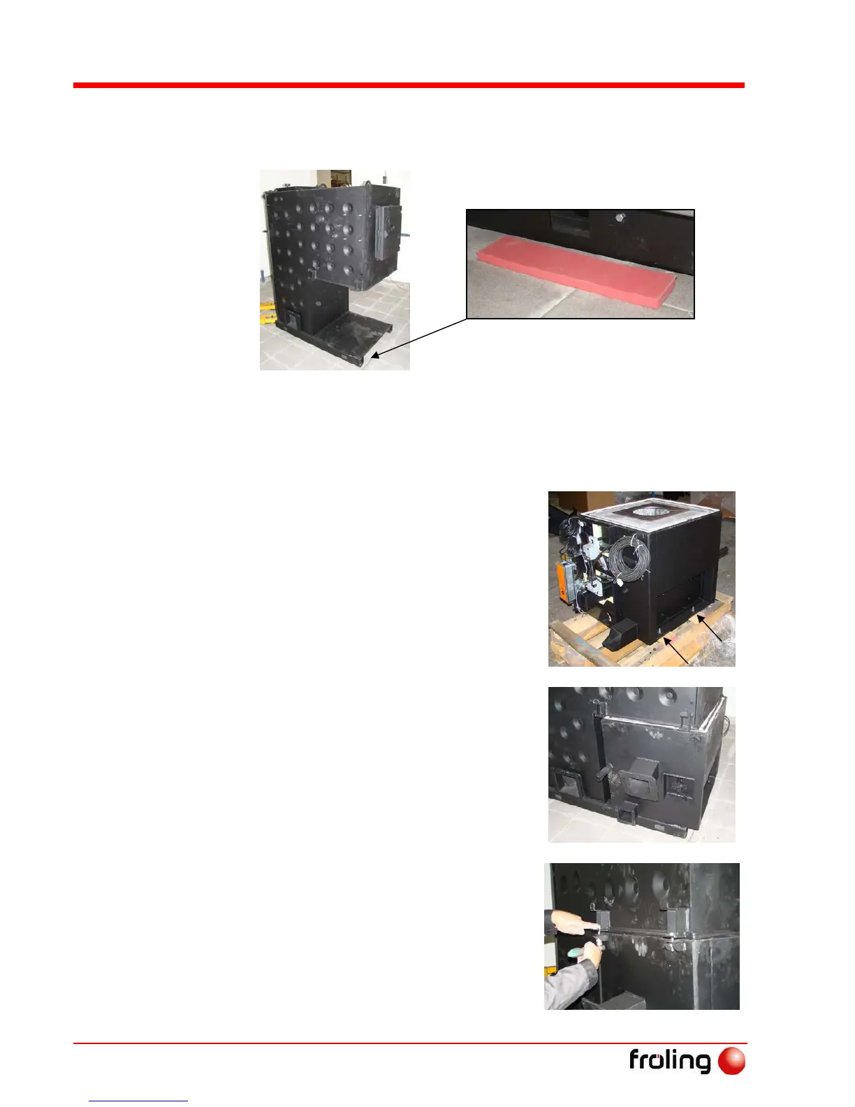
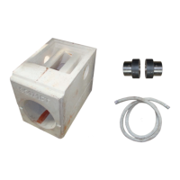
The chamber is delivered assembled and
tested:
U Unpack the chamber and remove
from the pallet
U M5 threaded holes on the chamber
opposite the operating side should
be closed with M5 hexagonal screws
or heat resistant adhesive tape
U Remove the chamber from the pallet
and position in the boiler
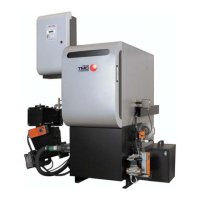
The connection flange for the
stoker duct should be on the left
or right depending on the side
where it is required
Follow the installation plan.
U Position the chamber so that the
holes are aligned with the securing
flaps
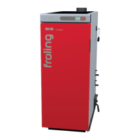
U Screw the chamber to the boiler
body by tightening the individual
screws equally
- 4 hexagonal screws M10x45
- 4 hexagonal nuts M10
- 4 spacer washers M10
The seal cord of the chamber must
also fit closely with the boiler.