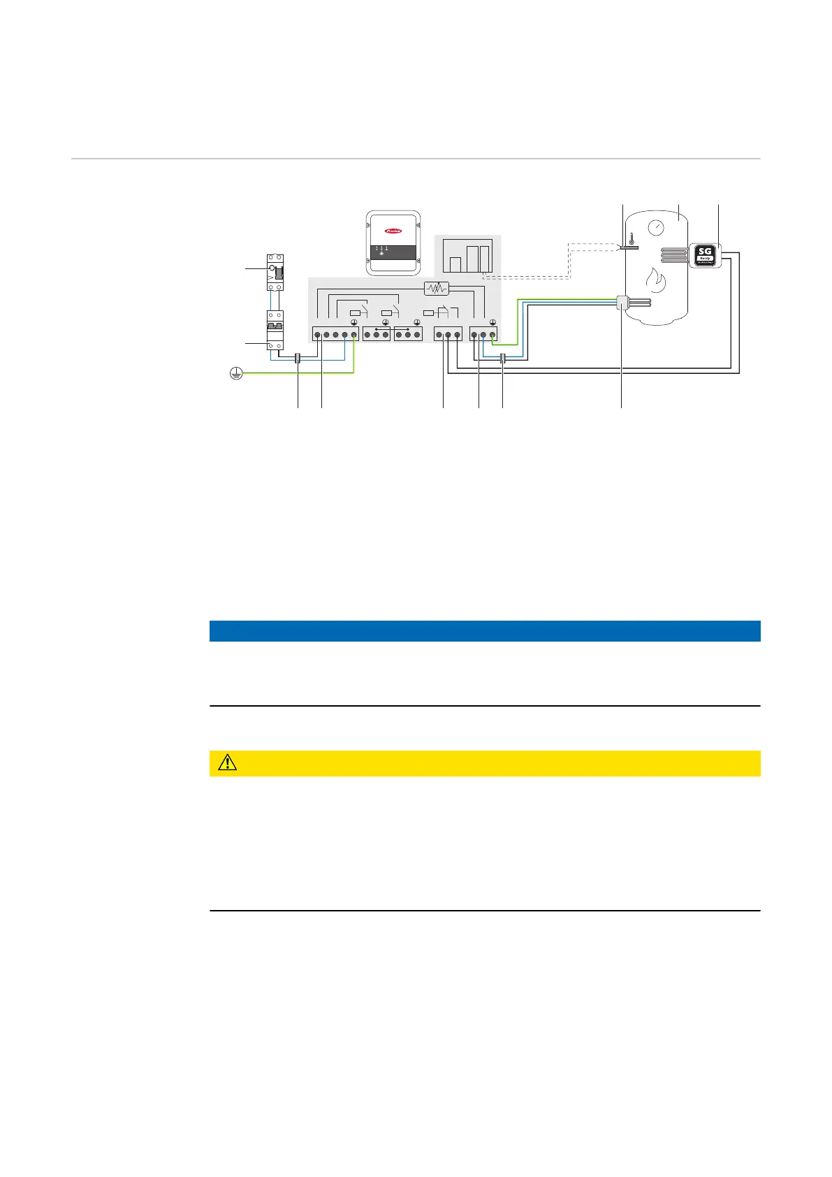
1-phase heating element up to 3 kW with heat
pump control
Application ex-
ample 3
L1 L2 L3 N L3 N L2 N NC W OUT NNO
R2 R3
LAN
RS485
PT1000
max. 16A
(2)
(8)
(6)
(1) (3)
(10)
(9)
External earth
(PE)
(4)(5)(5) (7)
(1) Temperature sensor PT1000
(2) Hot water boiler
(3) Heat pump with SG Ready control input
(4) Heating element (max. 3 kW)
(5) Ferrite rings (included in scope of delivery)
(6) Output up to 3 kW variable, max. 13 A resistive load, spring-loaded ter-
minal 1.5 - 2.5 mm²
(7) Multifunctional relay output
NOTE!
Relay contacts can oxidise.
The voltage must be at least 15 V and the current at least 2 mA, so that the relay
contacts do not oxidise.
(8) Input - grid supply 1x 230V network, spring-loaded terminal 1.5 - 2.5 mm²
CAUTION!
Danger due to contact with live, stripped wires
A short circuit can be triggered and damage the device.
▶
Carry out all connection work in accordance with the applicable electrotech-
nical guidelines and regulations.
▶
Observe the maximum stripping length of 10 mm.
▶
When connecting the phases, tie the individual wires together with a cable tie
immediately before the terminal.
(9) Residual-current circuit breaker
(10) Automatic circuit breaker max. B16A
The Fronius Smart Meter records the current power at the feed-in point and
transfers the data to the inverter. By controlling the Ohmpilot, the inverter ad-
justs any surplus energy that is available to zero. Specifically, this takes place by
continuously adjusting the heating element connected to the Ohmpilot and by
targeted switching on of the heat pump.
For activation, the heat pump must have a control input (SG Ready or approval
from grid operator). The heat pump can be switched from normal operation to
26