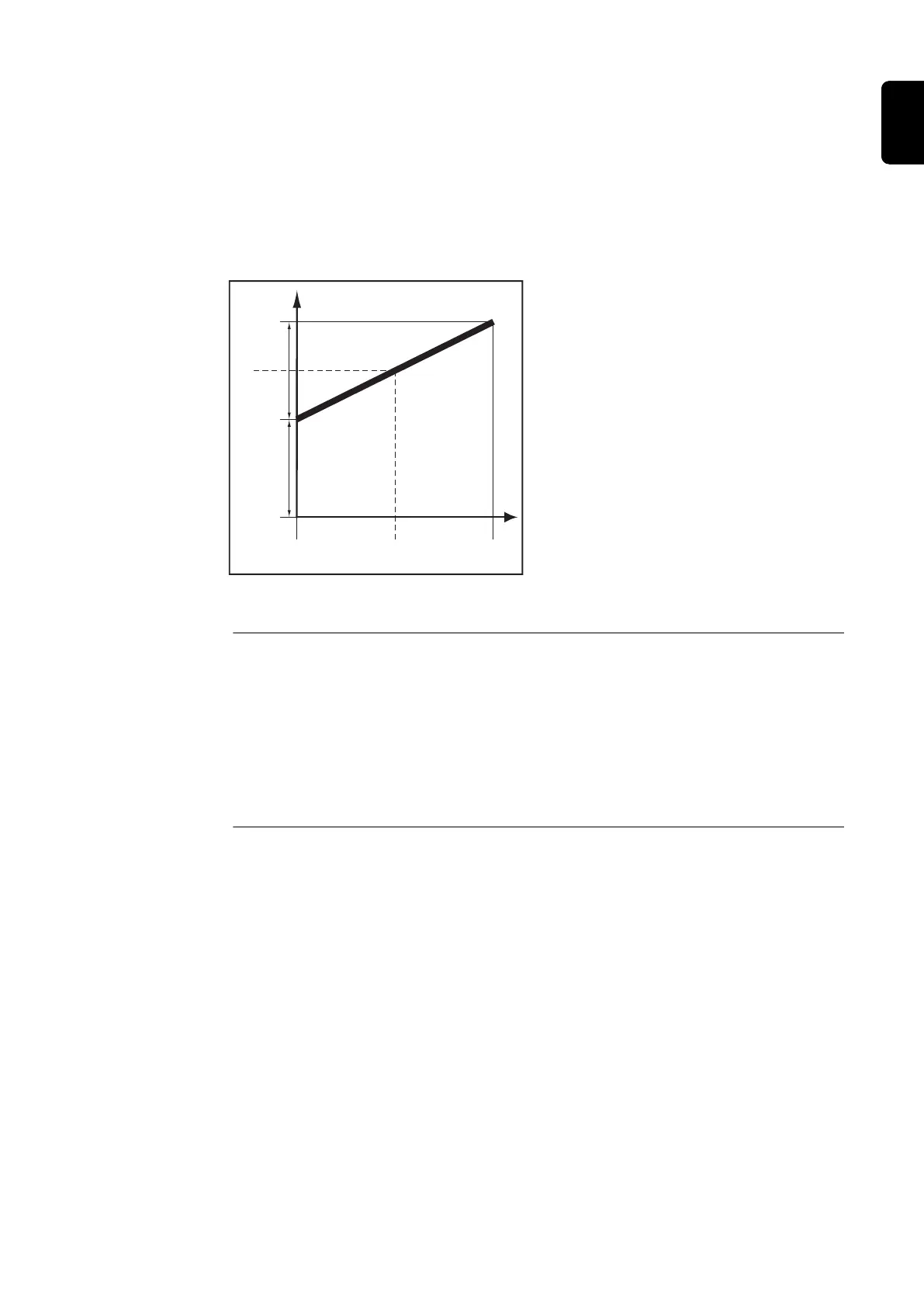
IMPORTANT! The values set for the 'post-flow lmin' and 'post-flow lmax' welding para-
meters are added together. For example, if both welding parameters are at maximum
(25 s / 40 s), the gas post-flow will last:
- 25 s at minimum welding current
- 65 s at maximum welding current
- 37.5 s if the welding current is exactly half the maximum, etc.
If Aut is selected, the gas post-flow time is calculated automatically. This takes the
selected process (AC or DC welding) into account.
Legend:
(1).... Gas post-flow time at any given
moment
(2).... Welding current at any given
moment
G-H.... Post-flow lmax
G-L .... Post-flow lmin
Gas post-flow time as a function of the welding current
Gas qtity
Command value for protective gas shield flow (only with the "digital gas control"
option)
Unit l/min cfh
Setting range OFF / 5.0 - max. OFF / 10.71 - max.
Factory setting 15 32.14
IMPORTANT! Please refer to "Digital Gas Control" operating instructions for more
detailed explanations of the "gas flow rate" welding parameter.
Gas correction
(only with the “Digital Gas Control“ option)
Unit -
Setting range AUT / 1.0 - 10.0
Factory setting AUT
IMPORTANT! Please refer to "Digital Gas Control" operating instructions for more
detailed explanations of the "gas correction" welding parameter.
119
EN

 Loading...


