6.2 Selecting Wires and Crimp Terminals
6-3
Chap. 6 SELECTING PERIPHERAL EQUIPMENT
Currents Flowing across the Inverter Terminals
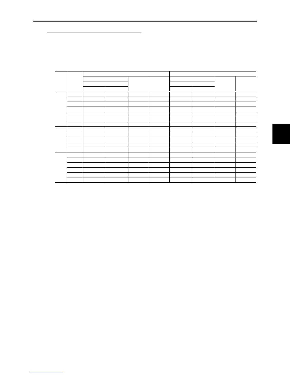
Table 6.1 summarizes average (effective) electric currents flowing across the terminals of each inverter
model for ease of reference when selecting peripheral equipment, options and electric wires for each
inverter--including supplied power voltage and applicable motor rating.
Table 6.1 Currents Flowing through Inverter
230 V/460 V (380 V), 50 Hz 230 V (200 V)/460 V (380 V), 60 Hz
Input RMS current (A) Input RMS current (A)
w/ DCR w/o DCR w/ DCR w/o DCR
1/8 0.57 1.1 0.70 - 0.51 (0.55) 1.1 (1.1) 0.62 (0.67) -
1/4 0.93 1.7 1.1 - 0.85 (0.92) 1.7 (1.8) 1.0 (1.1) -
1/2 1.6 3.0 2.0 1.2 1.5 (1.6) 3.0 (3.0) 1.8 (2.0) 1.2
1 3.0 5.1 3.7 1.6 2.8 (3.0) 5.0 (5.3) 3.4 (3.7) 1.6
2 5.7 9.4 7.0 3.6 5.2 (5.6) 9.0 (9.5) 6.3 (6.9) 3.6
3 8.3 13.0 10.2 3.5 7.6 (8.3) 12.3 (13.2) 9.3 (10.1) 3.5
5 14.0 22.2 17.2 4.1 12.7 (13.9) 20.6 (22.2) 15.6 (17.0) 4.1
1/2 0.81 (0.85) 1.6 (1.7) 0.99 (1.0) 0.8 0.74 (0.85) 1.7 (1.7) 0.91 (1.0) 0.8
1 1.5 (1.6) 2.9 (3.0) 1.8 (1.9) 1.1 1.4 (1.6) 3.0 (3.0) 1.7 (2.0) 1.1
2 2.9 (3.0) 5.7 (5.7) 3.5 (3.6) 1.8 2.6 (3.0) 5.1 (5.9) 3.2 (3.6) 1.8
3 4.2 (4.4) 7.9 (7.9) 5.1 (5.3) 1.8 3.8 (4.3) 7.1 (8.2) 4.6 (5.3) 1.8
5 7.0 (7.3) 12.5 (13.0) 8.6 (9.0) 2.1 6.4 (7.3) 11.1 (12.9) 7.8 (8.9) 2.1
1/8 1.1 1.8 1.1 - 1.0 (1.1) 1.8 (1.8) 1.0 (1.1) -
1/4 2.0 3.2 2.0 - 1.8 (1.9) 3.1 (3.2) 1.8 (1.9) -
1/2 3.5 5.2 3.5 0.82 3.1 (3.4) 5.0 (5.4) 3.1 (3.4) 0.82
1 6.4 9.5 6.4 1.4 5.8 (6.3) 9.1 (9.7) 5.8 (6.3) 1.4
2 11.7 16.0 11.7 1.4 10.5 (11.3) 15.5 (16.4) 10.5 (11.3) 1.4
3 17.5 24.2 17.5 1.7 15.8 (17.0) 23.4 (24.8) 15.8 (17.0) 1.7
Power
supply
voltage
Three-
phase
230 V
Three-
phase
460 V
Single-
phase
230 V
Applicable
motor
rating
(HP)
DC link
bus current (A)
DC link
bus current (A)
Braking resistor
circuit current
(A)
DC reactor (DCR)
Braking resistor
circuit current
(A)
DC reactor (DCR)
- Inverter efficiency is calculated using values suitable for each inverter model. The input route mean
square (RMS) current is calculated according to the following conditions:
Power source capacity: 500 kVA; power source internal impedance: 5%
- The current listed in the above table will vary in inverse proportion to the power supply voltage, such as
230 VAC and 380 VAC.
- The braking current is always constant, independent of braking resistor specifications, including
built-in, standard and 10%ED models.

 Loading...


