8-32
8.7 Connection Diagrams
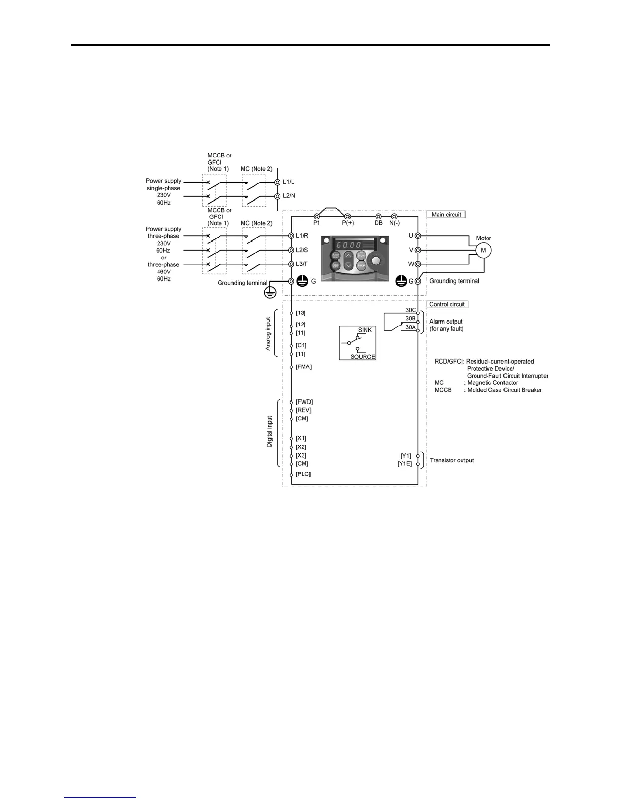
8.7.1 Keypad operation
The connection diagram below shows an example for a keypad operation with the built-in potentiometer
and keys.
(Note 1) Install a recommended molded case circuit breaker (MCCB) or a residual-current-operated protective device (RCD)/a
ground-fault circuit interrupter (GFCI) (with overcurrent protection) in the primary circuit of the inverter to protect wiring. At
this time, ensure that the circuit breaker capacity is equivalent to or lower than the recommended capacity.
(Note 2) A magnetic contactor (MC) should, if necessary, be mounted independent of the MCCB or GFCI to cut off the power fed to the
inverter. Refer to page 6-7 for details. MCs or solenoids that will be installed close to the inverter require surge absorbers to be
connected in parallel to their coils.

 Loading...


