4.1 Symbols Used in the Block Diagrams and their Meanings
4-1
Chap. 4 BLOCK DIAGRAMS FOR CONTROL LOGIC
FRENIC-Mini inverters are equipped with a number of function codes to match a variety of motor operations
required in your system. Refer to Chapter 9 "FUNCTION CODES" for details of the function codes.
The function codes have functional relationship with each other. Several special function codes also work with
execution priority with each other depending upon their data settings.
This chapter contains the main block diagrams for control logic in the inverter and describes the relationship
between the inverter's logic and function codes. It is important to fully understand this relationship and to set the
function code data correctly.
The block diagrams contained in the chapter show only function codes having mutual relation. For the function
codes that work stand-alone and for details of individual function codes, refer to Chapter 9 "FUNCTION
CODES."
4.1 Symbols Used in the Block Diagrams and their Meanings
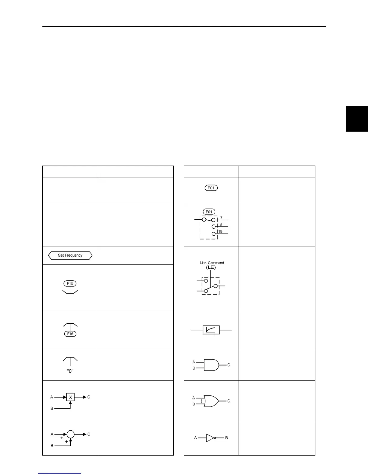
Table 4.1 lists the symbols commonly used in the block diagrams and their meanings with some examples.
Table 4.1 Symbols and Meanings
Symbol Meaning Symbol Meaning
[FWD],[Y1]
(etc.)
Input/output signals to/from
the inverter's control
terminal block.
Function code.
(FWD),(REV)
(etc.)
Control commands assigned
to the control terminal block
input signals.
Switch controlled by a
function code. Numbers
assigned to the terminals
express the function code
data.
Internal control command
for inverter logic.
High limiter: Limits peak
value by a constant or by
data set to the function code.
Switch controlled by an
internal control command. In
the example shown at the
left, the link operation
command (LE) is assigned to
one of the digital input
terminals from [X1] to [X3],
which then controls the
switch.
Low limiter: Limits the
bottom value by a constant
or by data set to the function
code.
Low-pass filter: Features
appropriate characteristics
by changing the time
constant through the
function code data.
Zero limiter: Keeps data
from dropping to a negative
value.
AND logic: In normal logic
systems, only if A = ON and
B = ON, then C = ON.
Otherwise, C = OFF.
Gain multiplier for set
frequencies given by current
and/or voltage input or for
analog output signals.
C = A u B
OR logic: In normal logic
systems, if any inputs are
ON, then C = ON. Only if all
inputs are OFF, then C =
OFF.
Adder for 2 signals or
values. C = A + B
If B is negative then C = A –
B.
NOT logic: In normal logic
systems, if A = ON, then B =
OFF and vice versa.

 Loading...


