App. B
Japanese Guideline for Suppressing Harmonics for Customers Receiving High Voltage or Special High Voltage
A-13
App.
(2) Regulation
The level (calculated value) of the harmonic current that flows from the customer's receiving point out to
the system is subjected to the regulation. The regulation value is proportional to the contract demand. The
regulation values specified in the guideline are shown in Table B.1.
Appendix B.2 gives you some supplemental information with regard to estimation for the equivalent
capacity of the inverter for compliance to "Japanese guideline for suppressing harmonics by customers
receiving high voltage or special high voltage."
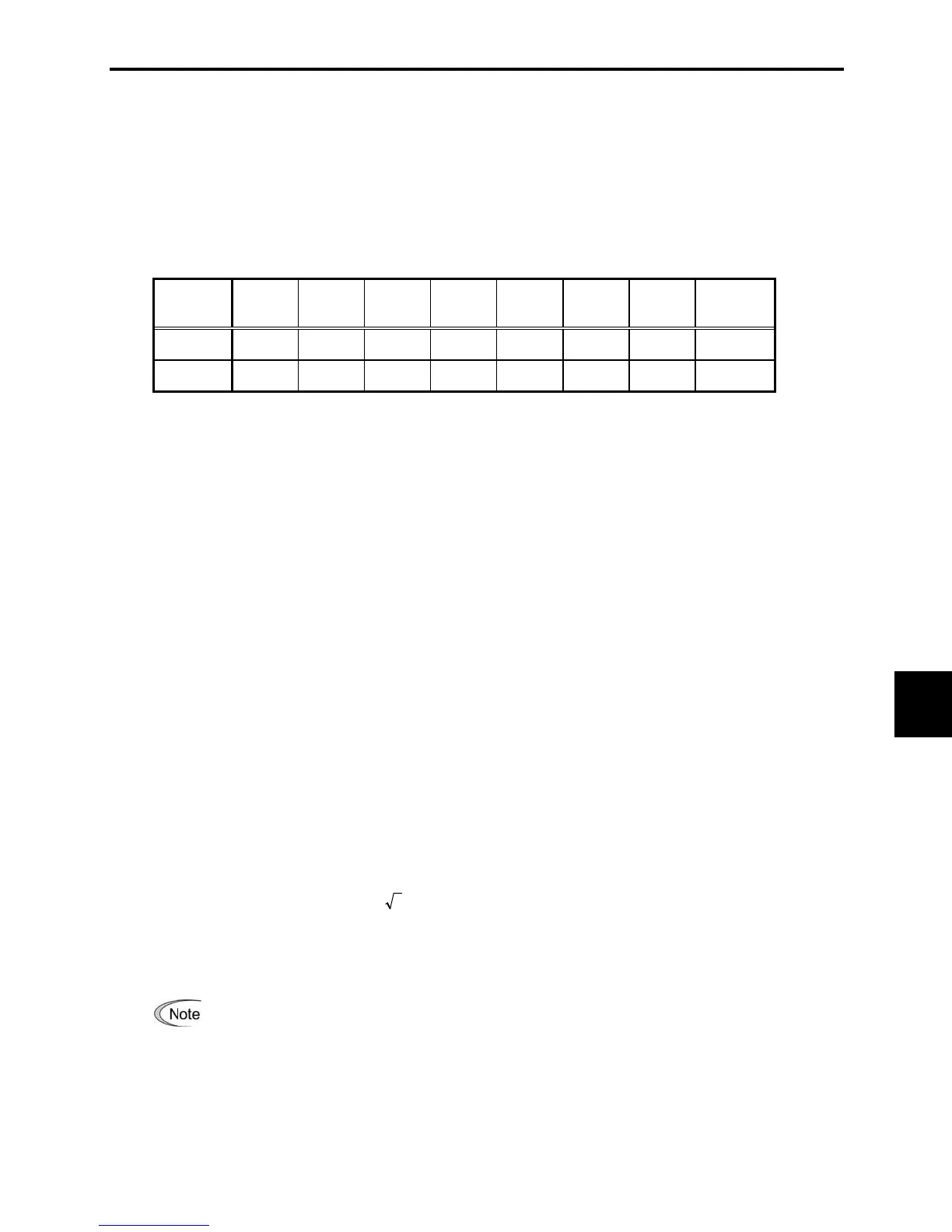
Table B.1 Upper Limits of Harmonic Outflow Current per kW of Contract Demand (mA/HP)
Receiving
voltage
5th 7th 11th 13th 17th 19th 23rd
Over
25th
6.6 kV 3.5 2.5 1.6 1.3 1.0 0.90 0.76 0.70
22 kV 1.8 1.3 0.82 0.69 0.53 0.47 0.39 0.36
(3) When the regulation applied
The guideline has been applied. As the application, the estimation for "Voltage waveform distortion rate"
required as the indispensable conditions when entering into the consumer's contract of electric power is
already expired.
B.2 Compliance to the harmonic suppression for customers receiving high
voltage or special high voltage
When calculating the required matters related to inverters according to the guideline, follow the terms
listed below. The following descriptions are based on "Technical document for suppressing harmonics"
(JEGE 9702-1995) published by the Japan Electrical Manufacturer's Association (JEMA).
[ 1 ] Calculation of equivalent capacity (Pi)
The equivalent capacity (Pi) may be calculated using the equation of (input rated capacity) x (conversion
factor). However, catalogs of conventional inverters do not contain input rated capacities, so a description
of the input rated capacity is shown below:
(1) "Inverter rated capacity" corresponding to "Pi"
- In the guideline, the conversion factor of a 6-pulse converter is used as reference conversion factor 1. It
is, therefore, necessary to express the rated input capacity of inverters in a value including harmonic
component current equivalent to conversion factor 1.
- Calculate the input fundamental current I
1 from the kW rating and efficiency of the load motor, as well
as the efficiency of the inverter. Then, calculate the input rated capacity as shown below:
)kVA(01.0228/100
I
tage)supply vol(power3capacityratedInput
1
uuu
where 1.0228 is the 6-pulse converter's value of (effective current)/(fundamental current).
- When a general-purpose motor or inverter motor is used, the appropriate value shown in Table B.2 can
be used. Select a value based on the kW rating of the motor used, irrespective of the inverter type.
The input rated capacity shown above is for the dedicated use in the equation to calculate
capacity of the inverters, following the guideline. Note that the capacity can not be applied to
the reference for selection of the equipment or wires to be used in the inverter input circuits.
For selection of capacity for the peripheral equipment, refer to the catalogs or technical documents
issued from their manufacturers.

 Loading...


