6.4 Selecting Options
6-13
Chap. 6 SELECTING PERIPHERAL EQUIPMENT
6.4 Selecting Options
6.4.1 Peripheral equipment options
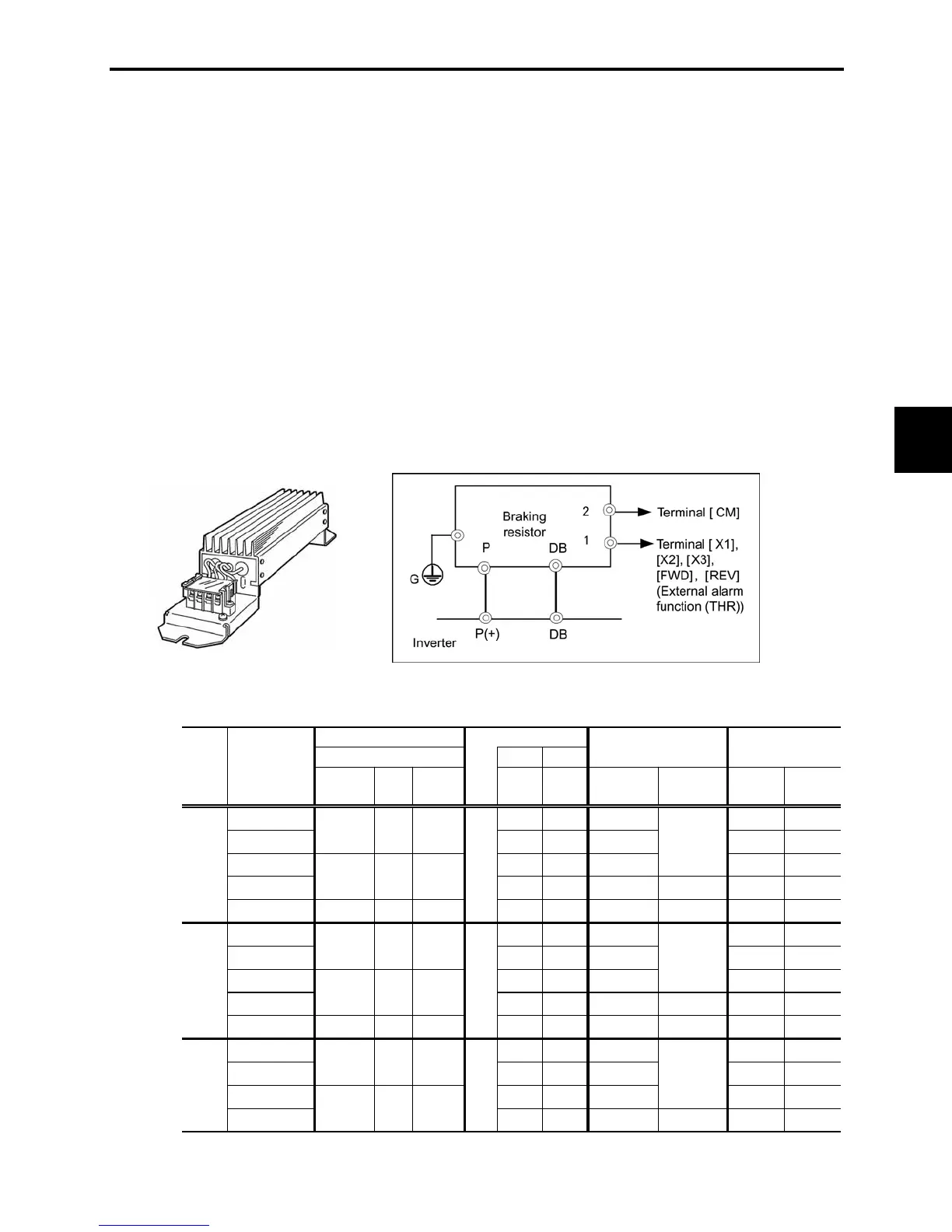
[ 1 ] Braking resistors
A braking resistor converts regenerative energy generated from deceleration of the motor and converts it
to heat for consumption. Use of a braking resistor results in improved deceleration performance of the
inverter.
Refer to Chapter 7, Section 7.2 "Selecting a Braking Resistor."
[ 1.1 ] Standard model
The standard model of a braking resistor integrates a facility that detects the temperature on the heat sink
of the resistor and outputs a digital ON/OFF signal if the temperature exceeds the specified level (as an
overheating warning signal). To ensure that the signal is recognized at one of the digital input terminals of
the FRENIC-Mini, assign the external alarm (THR) to any of terminals [X1] to [X3], [FWD] and [REV].
Connect the assigned terminal to terminal [1] of the braking resistor. Upon detection of the warning signal
(preset detection level: 150qC (302qF)), the inverter simultaneously transfers to Alarm mode, displays
alarm
J
on the LED monitor and shuts down its power output.
Figure 6.6 Braking Resistor (Standard Model) and Connection Example
Table 6.7 Braking Resistor (Standard Model)
Option
Braking resistor 50 Hz 60 Hz
FRNF50C1
-2U
35.6
(4.02)
29.4
(3.32)
9 0.059 22
FRN001C1
-2U
67.0
(7.57)
55.3
(6.25)
17 0.091 18
FRN002C1
-2U
133
(15.0)
110
(12.4)
34 0.101 10
FRN003C1
-2U
195
(22.0)
161
(18.2)
33 30 0.103 7
FRN005C1
-2U DB3.7-2 1 33
328
(37.1)
270
(30.5)
37 20 0.124 5
FRNF50C1
-4U
35.6
(4.02)
29.4
(3.32)
9 0.059 22
FRN001C1
-4U
67.0
(7.57)
55.3
(6.25)
17 0.091 18
FRN002C1
-4U
133
(15.0)
110
(12.4)
34 0.101 10
FRN003C1
-4U
195
(22.0)
161
(18.2)
33 30 0.103 7
FRN005C1
-4U DB3.7-4 1 130
328
(37.1)
270
(30.5)
37 20 0.124 5
FRNF50C1
-7U
35.6
(4.02)
29.4
(3.32)
9 0.059 22
FRN001C1
-7U
67.0
(7.57)
55.3
(6.25)
17 0.091 18
FRN002C1
-7U
133
(15.0)
110
(12.4)
34 0.101 10
FRN003C1
-7U
195
(22.0)
161
(18.2)
33 30 0.103 7
Duty cycle
(%ED)
Repetitive braking
(100 sec or less cycle)
Inverter type
Q'ty
Resistance
(
:
)
Max. braking torque (%)
Type
Continuous braking (
100%
torque conversion value)
Discharging
capability
(kWs)
150
140
Average
loss
(HP)
100
1
1
1
160
200
45
Power
supply
voltage
Three-
phase
230 V
Three-
phase
460 V
Single-
phase
230 V
DB2.2-4
150
DB2.2-2
DB2.2-2
lb-in
(N·m)
lb-in
(N·m)
DB0.75-2
100
140
DB0.75-2 1
150
45
45
Braking time
(s)
DB0.75-4
Notes: 1) A box (
) in the above table replaces S or E depending on enclosure.

 Loading...


