6-14
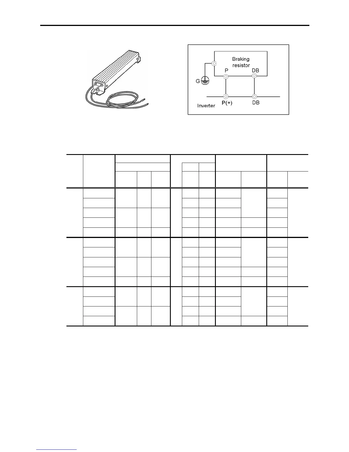
[ 1.2 ] 10%ED model
Figure 6.7 Braking Resistor (10 %ED Model) and Connection Example
Table 6.8 Braking Resistor (10 %ED Model)
Option
Braking resistor 50 Hz 60 Hz
FRNF50C1
-2U
35.6
(4.02)
29.4
(3.32)
90.027
FRN001C1
-2U
67.0
(7.57)
55.3
(6.25)
17 0.050
FRN002C1
-2U
133
(15.0)
110
(12.4)
34 0.101
FRN003C1
-2U
195
(22.0)
161
(18.2)
33 30 0.148
FRN005C1
-2U DB3.7-2C 1 33
328
(37.1)
270
(30.5)
37 20 0.248
FRNF50C1-4U
35.6
(4.02)
29.4
(3.32)
90.027
FRN001C1
-4U
67.0
(7.57)
55.3
(6.25)
17 0.050
FRN002C1
-4U
133
(15.0)
110
(12.4)
34 0.101
FRN003C1-4U
195
(22.0)
161
(18.2)
33 30 0.148
FRN005C1
-4U DB3.7-4C 1 130
328
(37.1)
270
(30.5)
37 20 0.248
FRNF50C1
-7U
35.6
(4.02)
29.4
(3.32)
90.027
FRN001C1
-7U
67.0
(7.57)
55.3
(6.25)
17 0.050
FRN002C1
-7U
133
(15.0)
110
(12.4)
34 0.501
FRN003C1
-7U
195
(22.0)
161
(18.2)
33 30 0.248
Power
supply
voltage
Inverter type
Max. braking torque (%)
Continuous braking (
100%
torque conversion value)
lb-in
(N·m)
lb-in
(N·m)
Repetitive braking
(100 sec or less cycle)
Type Q'ty
Resistance
(
:
)
Discharging
capability
(kWs)
Braking time
(s)
Average
loss
(HP)
Duty cycle
(%ED)
Three-
phase
230 V
DB0.75-2C 1 100
150
DB2.2-2C 1 40
Three-
phase
460 V
DB0.75-4C 1 200
150
DB2.2-4C 1 160
Single-
phase
230 V
DB0.75-2C 1 100
150
DB2.2-2C 1 40
45
45
45
10
10
10
Notes: 1) A box (
) in the above table replaces S or E depending on enclosure.
The 10 %ED braking resistor does not support overheating detection or warning output, so an electronic
thermal overload relay needs to be set up using function codes F50 and F51 to protect the braking resistor
from overheating.

 Loading...


