3.3 Programming Mode
3-17
Chap. 3 OPERATION USING THE KEYPAD
Hexadecimal expression
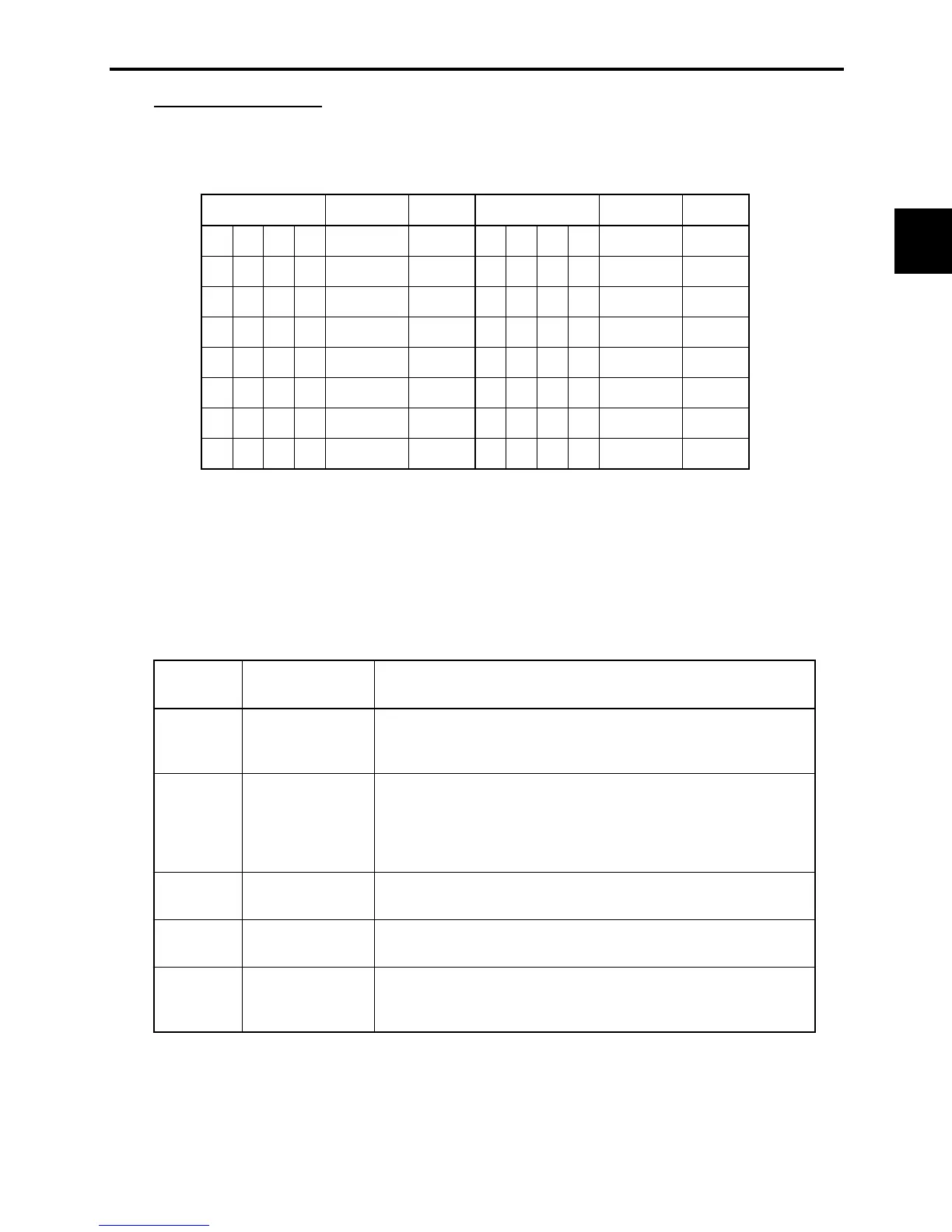
A 16-bit binary number is expressed in hexadecimal format (4 bits). Table 3.8 shows the expression
corresponding to decimals. The hexadecimals are shown as they appear on the LED monitor.
Table 3.8 Binary and Hexadecimal Conversion
Binary Hexadecimal Decimal Binary Hexadecimal Decimal
0 0 0 0
0 1 0 0 0
8
0 0 0 1
1 1 0 0 1
9
0 0 1 0
2 1 0 1 0
C
10
0 0 1 1
3 1 0 1 1
D
11
0 1 0 0
4 1 1 0 0
E
12
0 1 0 1
5 1 1 0 1
F
13
0 1 1 0
6 1 1 1 0
G
14
0 1 1 1
7 1 1 1 1
H
15
3.3.4 Checking I/O signal status--"I/O Checking"
With Menu #4 "I/O checking," you may display the status of external I/O signals without using a
measuring instrument. External signals that can be displayed include digital I/O signals and analog I/O
signals. Table 3.9 lists check items available. The status transition for I/O checking is shown in Figure
3.8.
Table 3.9 I/O Check Items
LED monitor
shows:
Display contents Description
A
I/O signals on the
control circuit
terminals
Shows the ON/OFF state of the digital I/O terminals. Refer to "[1]
Displaying control I/O signal terminals" on page 3-19 for details on
the display contents.
A
I/O signals on the
control circuit
terminals under
communication
control
Shows the ON/OFF state for the digital input terminals that received
a command via RS-485 communications. Refer to "[1] Displaying
control I/O signal terminals" on page 3-19 and "[2] Displaying
control I/O signal terminals under communication control" on page
3-20 for details on the display contents.
A
Input voltage on
terminal [12]
Shows the input voltage on terminal [12] in volts (V).
A
Input current on
terminal [C1]
Shows the input current on terminal [C1] in milliamperes (mA).
A
Output voltage to
analog meters
[FMA]
Shows the output voltage on terminal [FMA] in volts (V).

 Loading...


