3-16
Displaying running status
To display the running status in hexadecimal format, each state has been assigned to bit 0 to 15 as listed
in Table 3.6. Table 3.7 shows the relationship between each of the status assignments and the LED
monitor display. Table 3.8 gives the conversion table from 4-bit binary to hexadecimal.
Table 3.6 Running Status Bit Allocation
Bit Notation Content
15 BUSY 1 when function code data is being written.
14 Always 0.
13
WR
Always 0.
12 RL 1 when communications is effective (when run commands and set frequencies
commands are issued via communications).
11 ALM 1 when an alarm has occurred.
10 DEC 1 during deceleration.
9 ACC 1 during acceleration.
8 IL 1 during current limitation.
7 VL 1 under voltage control.
6 TL Always 0.
5 NUV 1 when DC link bus voltage has increased up to the specified level (0 for
undervoltage).
4 BRK Always 0.
3 INT 1 when the inverter output is shut down.
2 EXT 1 during DC braking.
1 REV 1 during running in the reverse direction.
0 FWD 1 during running in the forward direction.
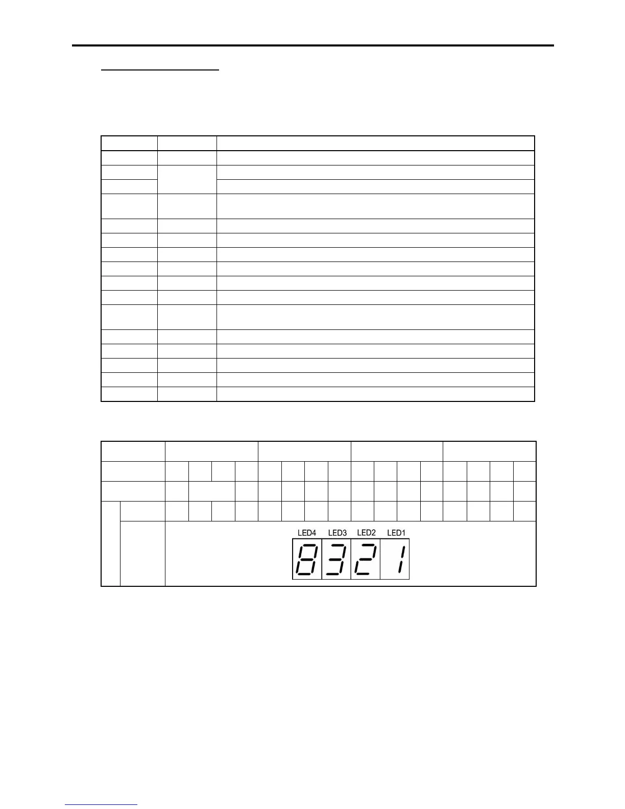
Table 3.7 Running Status Display
LED No. LED4 LED3 LED2 LED1
Bit 15 14 13 12 11 10 9 8 7 6 5 4 3 2 1 0
Notation BUSY WR RL ALM DEC ACC IL VL TL NUV BRK INT EXT REV FWD
Binary 1 0 0 0 0 0 1 1 0 0 1 0 0 0 0 1
Example
Hexa-
decimal
on the
LED
monitor

 Loading...


