6.4 Selecting Options
6-19
Chap. 6 SELECTING PERIPHERAL EQUIPMENT
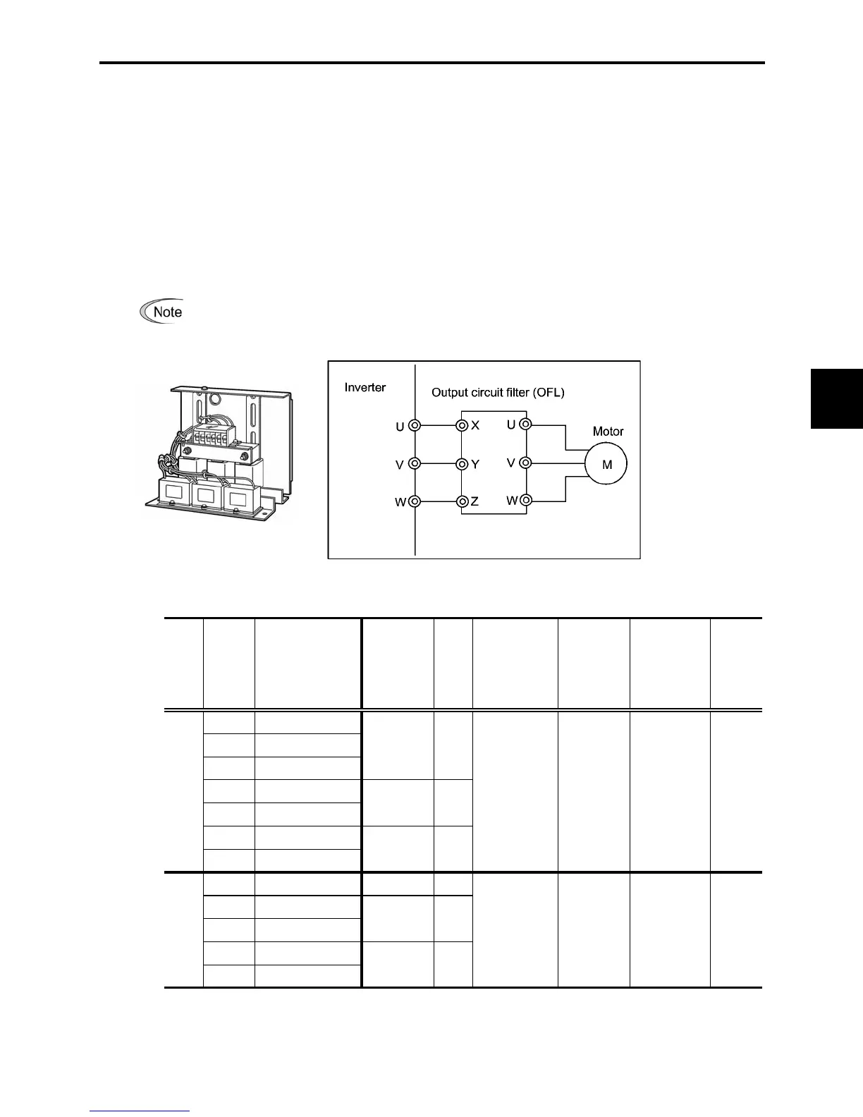
[ 4 ] Output circuit filters (OFLs)
Insert an OFL in the inverter power output circuit to:
- Suppress the voltage fluctuation at the motor power terminals
This protects the motor from insulation damage caused by the application of high voltage surge
currents from the 400 V class of inverters.
- Suppress leakage current (due to higher harmonic components) from the inverter output lines
This reduces the leakage current when the motor is connected by long power feed lines. Keep the
length of the power feed line less than 1300 ft (400 m).
- Minimize radiation and/or induction noise issued from the inverter output lines
OFLs are effective noise suppression device for long wiring applications such as that used at plants.
Use an ACR within the allowable carrier frequency range specified by function code F26.
Otherwise, the filter will overheat.
Figure 6.11 External View of Output Circuit Filter (OFL) and Connection Example
Table 6.12 Output Circuit Filter (OFL)
1/8
FRNF12C1-2U
1/4
FRNF25C1-2U
3
1/2
FRNF50C1-2U
150 % for 1 min. Three-phase
1
FRN001C1-2U
200 % for 0.5 sec 200 to 240 V 8 to 15 400
2
FRN002C1-2U
50/60 Hz
3
FRN003C1-2U
5
FRN005C1-2U
1/2
FRNF50C1-4U
OFL-0.4-4A 1.5
1
FRN001C1-4U
150% for 1min. Three-phase
2
FRN002C1-4U
200 % for 0.5 sec 380 to 480 V 0.75 to 15 400
3
FRN003C1-4U
50/60 Hz
5
FRN005C1-4U
OFL-3.7-2
Maximum
frequency
(Hz)
3.7
9
8
17
Rated
current
(A)
Overload
capability
Inverter
power
input
voltage
Carrier
frequency -
allowable
range
(kHz)
Three-
phase
230 V
OFL-3.7-4A
OFL-1.5-4A
Inverter type
Three-
phase
460 V
Power
supply
voltage
Filter type
Applicable
motor
rating
(HP)
OFL-0.4-2
OFL-1.5-2
Note 1: The OFL-***-4A models have no restrictions on carrier frequency.
Note 2: A box (
) in the above table replaces S or E depending on enclosure.

 Loading...


