6.2 Selecting Wires and Crimp Terminals
6-5
Chap. 6 SELECTING PERIPHERAL EQUIPMENT
■ If the internal temperature of your power control cabinet is 40qC (104qF) or below
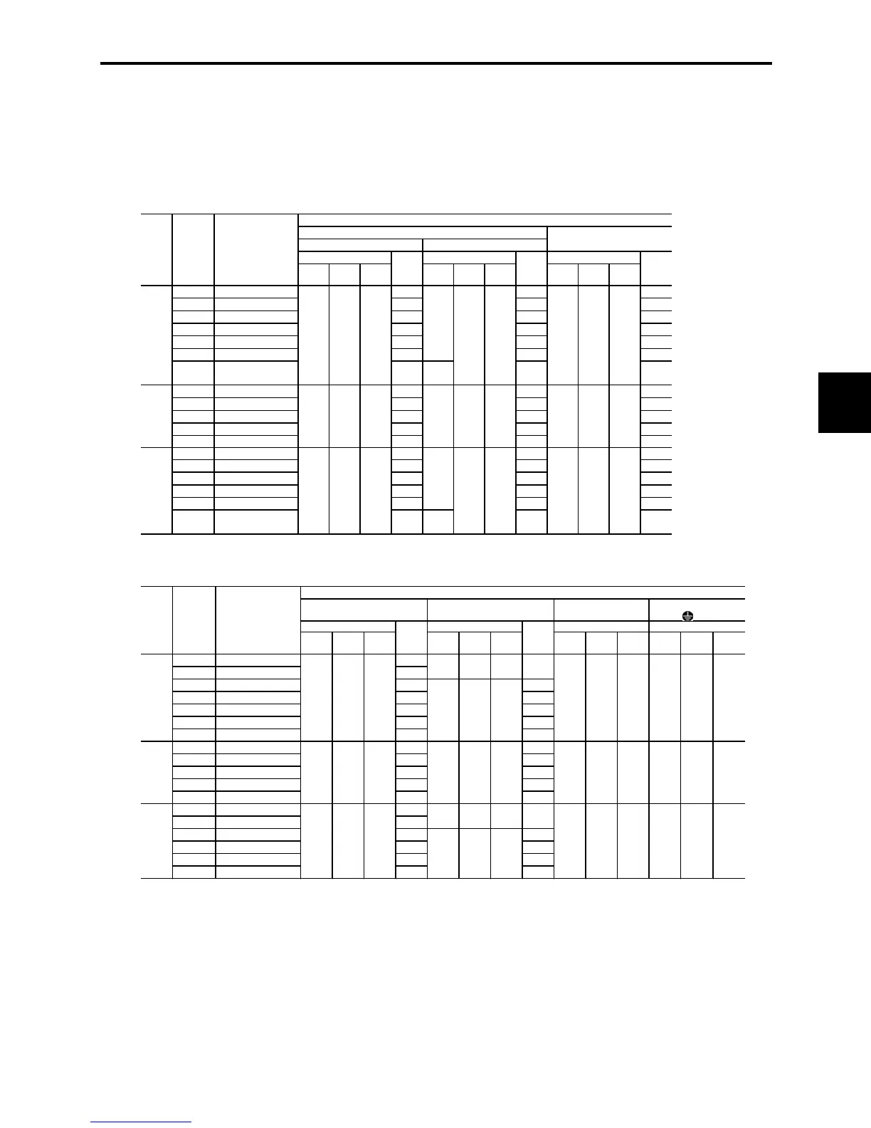
Table 6.3 Wire Size (for main circuit power input and inverter output)
Current Current Current
60°C
(140°F)
75°C
(167°F)
90°C
(194°F) (A)
60°C
(140°F)
75°C
(167°F)
90°C
(194°F) (A)
60°C
(140°F)
75°C
(167°F)
90°C
(194°F) (A)
1/8
FRNF12C1
-2U
0.57 1.1
0.8
1/4
FRNF25C1
-2U
0.93 1.8
1.5
1/2
FRNF50C1
-2U
1.6 3.1
3.0
1
FRN001C1
-2U
3.0 5.3
5.5
2
FRN002C1
-2U
5.7 9.5
8.0
3
FRN003C1
-2U
8.3 13.2
11
5
FRN005C1
-2U
14.0
0.005
(3.5)
22.2 17
1/2
FRNF50C1
-4U
0.85 1.7
1.5
1
FRN001C1
-4U
1.6 3.1
2.5
2
FRN002C1
-4U
3.0 5.9
3.7
3
FRN003C1
-4U
4.4 8.2
5.5
5
FRN005C1
-4U
7.3 13.0 9
1/8
FRNF12C1
-7U
1.1 1.8 0.8
1/4
FRNF25C1
-7U
2.0 3.3
1.5
1/2
FRNF50C1
-7U
3.5 5.4
3.0
1
FRN001C1
-7U
6.4 9.7
5.0
2
FRN002C1
-7U
11.6 16.4
8.0
3
FRN003C1
-7U
17.5
0.005
(3.5)
24.8 11
Inverter output [U , V , W]
Allowable temp.*1
Main circuit power input [L1/R , L2/S , L3/T] or [L1/L, L2/N]
w/ DC reactor (DCR) w/o DC reactor (DCR)
Allowable temp.*1 Allowable temp.*1
Three-
phase
230 V
0.003
(2.0)
0.003
(2.0)
0.003
(2.0)
0.003
(2.0)
0.003
(2.0)
0.003
(2.0)
0.003
(2.0)
0.003
(2.0)
0.003
(2.0)
Three-
phase
460 V
0.003
(2.0)
0.003
(2.0)
0.003
(2.0)
0.003
(2.0)
0.003
(2.0)
0.003
(2.0)
0.003
(2.0)
0.003
(2.0)
0.003
(2.0)
Single-
phase
230 V
0.003
(2.0)
0.003
(2.0)
0.003
(2.0)
0.003
(2.0)
0.003
(2.0)
0.003
(2.0)
0.003
(2.0)
0.003
(2.0)
0.003
(2.0)
Power
supply
voltage
Applicable
motor
rating
(HP)
Inverter type
Recommended wire size [inch
)]
Table 6.3 Cont. (for DC reactor, braking resistor, control circuit, and inverter grounding)
Current Current
60°C
(140°F)
75°C
(167°F)
90°C
(194°F) (A)
60°C
(140°F)
75°C
(167°F)
90°C
(194°F) (A)
60°C
(140°F)
75°C
(167°F)
90°C
(194°F)
60°C
(140°F)
75°C
(167°F)
90°C
(194°F)
1/8
FRNF12C1
-2U
0.7
1/4
FRNF25C1
-2U
1.1
1/2
FRNF50C1
-2U
2.0 1.2
1
FRN001C1
-2U
3.7 1.6
2
FRN002C1
-2U
7.0 3.6
3
FRN003C1
-2U
10.2 3.5
5
FRN005C1
-2U
17.2 4.1
1/2
FRNF50C1
-4U
1.0 0.8
1
FRN001C1
-4U
1.9 1.1
2
FRN002C1
-4U
3.6 1.8
3
FRN003C1
-4U
5.3 1.8
5
FRN005C1
-4U
9.0 2.1
1/8
FRNF12C1
-7U
1.1
1/4
FRNF25C1
-7U
2.0
1/2
FRNF50C1
-7U
3.5 0.82
1
FRN001C1
-7U
6.4 1.4
2
FRN002C1
-7U
11.7 1.4
3
FRN003C1
-7U
17.5 1.7
0.003
(2.0)
0.003
(2.0)
0.003
(2.0)
0.003
(2.0)
0.001
(0.5)
0.001
(0.5)
0.003
(2.0)
0.003
(2.0)
0.003
(2.0)
Single-
phase
230 V
0.003
(2.0)
0.003
(2.0)
0.003
(2.0)
----
0.001
(0.5)
0.001
(0.5)
0.001
(0.5)
0.003
(2.0)
0.003
(2.0)
0.003
(2.0)
0.003
(2.0)
0.003
(2.0)
0.001
(0.5)
Three-
phase
460 V
0.003
(2.0)
0.003
(2.0)
0.003
(2.0)
0.003
(2.0)
0.003
(2.0)
0.003
(2.0)
0.003
(2.0)
0.003
(2.0)
0.001
(0.5)
0.001
(0.5)
0.001
(0.5)
0.003
(2.0)
Allowable temp.*1 Allowable temp.*1
Three-
phase
230 V
0.003
(2.0)
0.003
(2.0)
0.003
(2.0)
----
Power
supply
voltage
Applicable
motor
rating
(HP)
Inverter type
Recommended wire size [inch
2
(mm
2
)]
DC reactor
[P1, P(+)]
Braking resistor
[P(+), DB]
Control circuit
Inverter grounding
[G]
Allowable temp.*1 Allowable temp.*1
*1 Assuming the use of bare wiring (without rack or duct): 600 V class of vinyl-insulated IV wires for 60qC (140qF), 600 V
class of polyethylene-insulated HIV wires for 75qC (167qF), and 600 V class of polyethylene-insulated cross-link wires
for 90qC (194qF).
Notes: 1) A box (
) in the above tables replaces S or E depending on enclosure.
If environmental requirements such as power supply voltage and ambient temperature differ from
those listed above, select wires suitable for your system by referring to Table 6.1 and Appendices,
App. F "Allowable Current of Insulated Wires."

 Loading...


