6.4 Selecting Options
6-17
Chap. 6 SELECTING PERIPHERAL EQUIPMENT
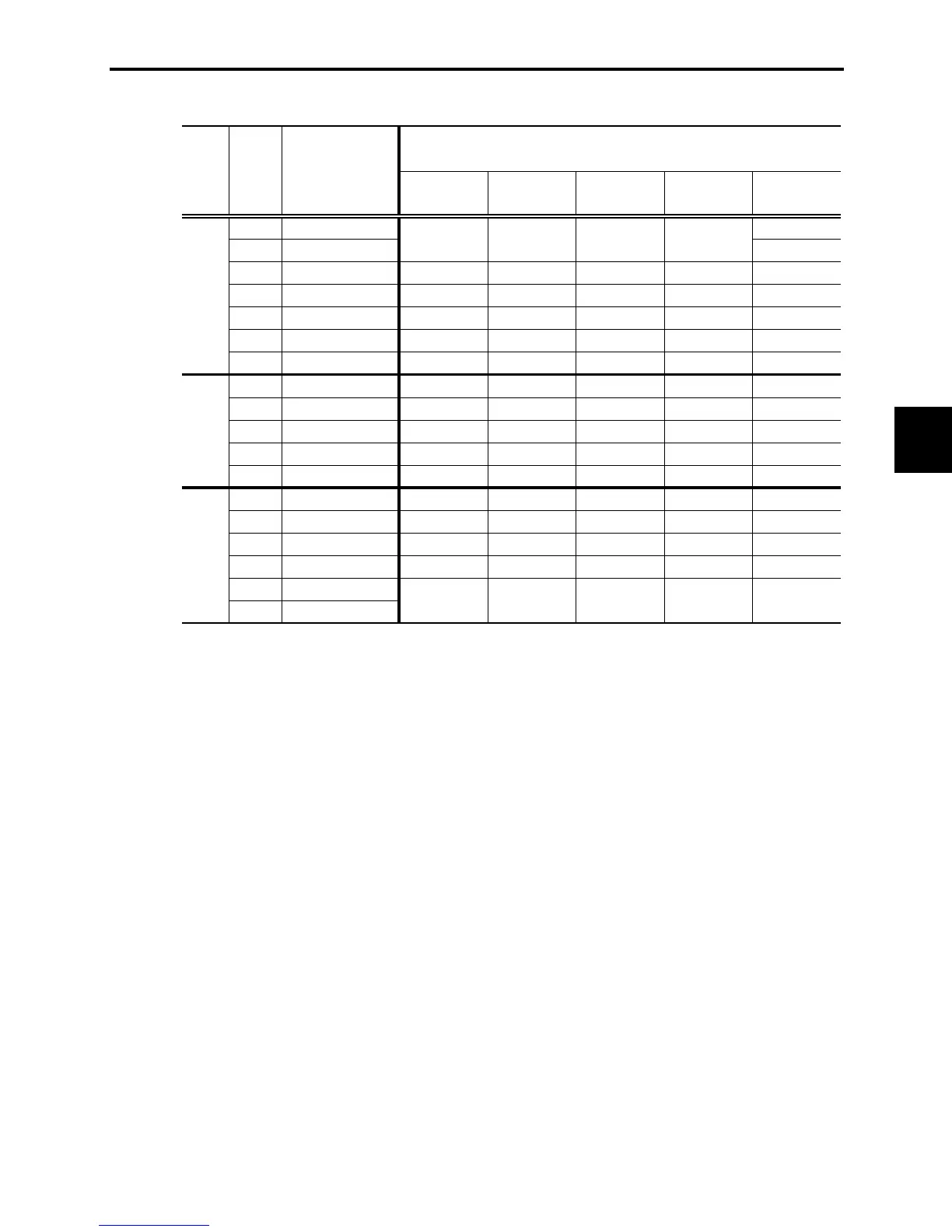
Table 6.10 DC Reactors (DCRs)
1/8
FRNF12C1-2U
0.8
1/4
FRNF25C1-2U
1.6
1/2
FRNF50C1-2U
DCR2-0.4 3.0 12 280 1.9
1
FRN001C1-2U
DCR2-0.75 5.0 7.0 123 2.8
2
FRN002C1-2U
DCR2-1.5 8.0 4.0 57.5 4.6
3
FRN003C1-2U
DCR2-2.2 11 3.0 43 6.7
5
FRN005C1-2U
DCR2-3.7 18 1.7 21 8.8
1/2
FRNF50C1-4U
DCR4-0.4 1.5 50 970 2.0
1
FRN001C1-4U
DCR4-0.75 2.5 30 440 2.5
2
FRN002C1-4U
DCR4-1.5 4.0 16 235 4.8
3
FRN003C1-4U
DCR4-2.2 5.5 12 172 6.8
5
FRN005C1-4U
DCR4-3.7 9.0 7.0 74.5 8.1
1/8
FRNF12C1-7U
DCR2-0.2 1.5 20 660 1.6
1/4
FRNF25C1-7U
DCR2-0.4 3.0 12 280 1.9
1/2
FRNF50C1-7U
DCR2-0.75 5.0 7.0 123 2.8
1
FRN001C1-7U
DCR2-1.5 8.0 4.0 57.5 4.6
2
FRN002C1-7U
3
FRN003C1-7U
21 8.8
Type
DCR2-3.7 18 1.7
Rated current
(A)
Inductance
(mH)
Coil resistance
(m
:
)
Generated loss
(W)
Power
supply
voltage
Three-
phase
230 V
Inverter type
DC reactor (DCR)
20 660
Applicable
motor
rating
(HP)
Three-
phase
460 V
Single-
phase
230 V
DCR2-0.2 1.5
Note 1: Generated losses listed in the above table are approximate values that are calculated according to the following
conditions:
- The power source is 3-phase 230 V/460 V 60 Hz with 0% interphase voltage unbalance ratio.
- The power source capacity uses the larger of either 500 kVA or 10 times the rated capacity of the inverter.
- The motor is a 4-pole standard model at full load (100%).
- An AC reactor (ACR) is not connected.
Note 2: A box (
) in the above table replaces S or E depending on enclosure.

 Loading...


