Turning ON or OFF [X1], [X2], [X3], [FWD], or [REV] using a relay contact
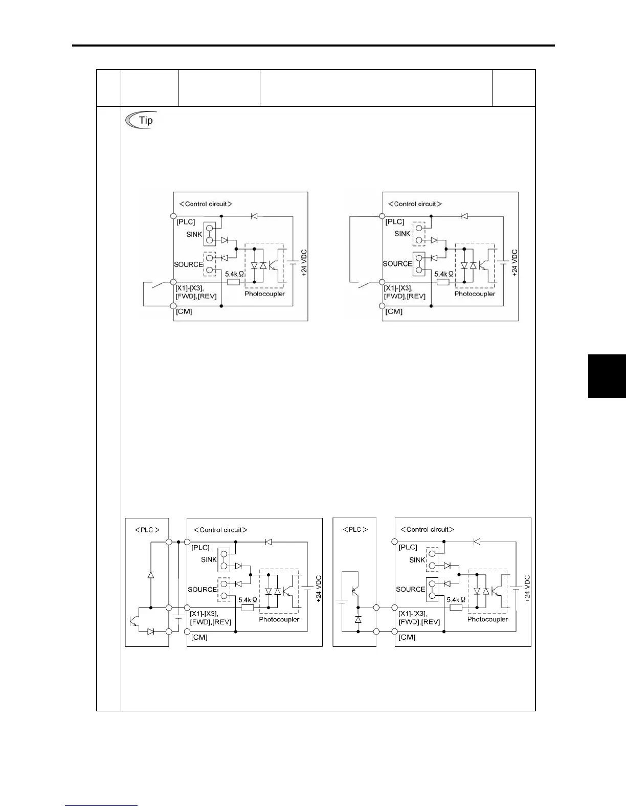
Figure 8.3 shows two examples of a circuit that turns ON or OFF control signal input
[X1], [X2], [X3], [FWD], or [REV] using a relay contact. Circuit (a) has a connecting
jumper applied to SINK, whereas circuit (b) has it applied to SOURCE.
NOTE: To configure this kind of circuit, use a highly reliable relay
(Recommended product: Fuji control relay Model HH54PW.)
(a) With a jumper applied to SINK (b) With a jumper applied to SOURCE
Figure 8.3 Circuit Configuration Using a Relay Contact
Turning ON or OFF [X1], [X2], [X3], [FWD], or [REV] using a programmable
logic controller (PLC)
Figure 8.4 shows two examples of a circuit that turns ON or OFF control signal input
[X1], [X2], [X3], [FWD], or [REV] using a programmable logic controller (PLC). Circuit
(a) has a connecting jumper applied to SINK, whereas circuit (b) has it applied to
SOURCE.
In circuit (a) below, short-circuiting or opening the transistor's open collector circuit in
the PLC using an external power source turns ON or OFF control signal [X1], [X2], [X3],
[FWD], or [REV]. When using this type of circuit, observe the following:
• Connect the + node of the external power source (which should be isolated from the
PLC's power) to terminal [PLC] of the inverter.
• Do not connect terminal [CM] of the inverter to the common terminal of the PLC.
Digital input
(a) With a jumper applied to SINK (b) With a jumper applied to SOURCE
Figure 8.4 Circuit Configuration Using a PLC
For details about the jumper setting, refer to the FRENIC-Mini Instruction Manual, Chapter 2, Section
2.3.8 "Switching of SINK/SOURCE (jumper switch)."

 Loading...


