9.2 Details of Function Codes
9-39
Chap. 9 FUNCTION CODES
E20 and E27
Status Signal Assignment to [Y1], [30A], [30B] and [30C]
E20 to E27 may assign output signals (listed below) to terminals [Y1] (transistor switch) and
[30A], [30B] and [30C] (mechanical relay contacts) which are general-purpose programmable
output terminals.
These function codes may also switch the logic system between normal and negative to define
the property of those output terminals so that the inverter logic may interpret either the ON or
OFF status of each terminal as active.
Terminals [30A], [30B], and [30C] are mechanical relay contacts. In the normal logic, if an
alarm occurs, the relay will be excited so that [30A] and [30C] will be short-circuited, signaling
an occurrence of the error to external equipment. On the other hand, in the negative logic, the
relay will cut off the excitation current to open [30A] and [30C]. This may be useful for the
implementation of failsafe power systems.
The default setting is normal logic, that is "Active ON."
To assign negative logic input to any input terminal, set the function code to the value of 1000s
shown in ( ) in the table below. To keep explanations as simple as possible, the examples shown
below are all written for the normal logic system.
When negative logic is active, the inverter switches all output signals to the active
side (for example, the alarm side). To avoid system malfunctions caused by this,
interlock the signals to keep them ON using an external power source. To use
negative logic with the output signal, set the data of 1000s in ( ) as listed in the table
below.
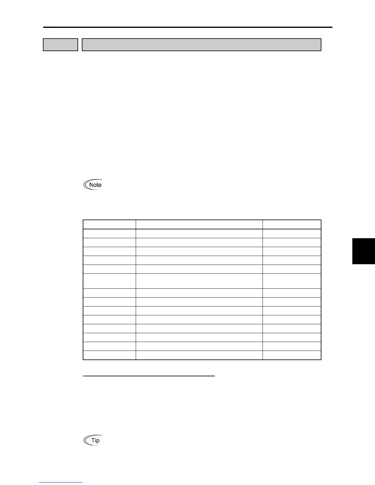
Data for E20 or E27 To assign the following status signals to terminals: Output signal symbols
0 (1000) Inverter running (Speed > 0) (RUN)
1 (1001) Frequency arrival signal (FAR)
2 (1002) Frequency detection (FDT)
3 (1003) Undervoltage detection (LU)
5 (1005) Torque limiting (Current limiting) (IOL)
6 (1006) Auto-restart after recovery from instantaneous
power failure
(IPF)
7 (1007) Motor overload early warning (OL)
26 (1026) Retry in operation (TRY)
30 (1030) Lifetime alarm (LIFE)
35 (1035) Inverter running (RUN2)
36 (1036) Overload prevention control (OLP)
37 (1037) Current detection (ID)
41 (1041) Low level current detection (IDL)
99 (1099) Alarm relay contact output (for any fault) (ALM)
Terminal function assignment and data setting
Inverter running (Speed > 0)--(RUN)
(Function code data = 0)㩷
This output signal is used to tell the external equipment that the inverter is running with a speed
greater than 0. It switches ON when the inverter output frequency exceeds the start frequency of
the motor. It switches OFF when the output frequency is less than the start frequency or the
inverter is DC-braking the motor.
If this signal is assigned to terminal [Y1] in negative logic (active OFF), it can be
used to indicate the inverter stopping its output.

 Loading...


