elect the number of stop bits.
- Setting for FRENIC Loader: The loader
automatically sets it to 1 bit.
The Modbus RTU protocol automatically
determines number of the parity bits
associated with its parity bit property so
no setting is required.
No-response error detection time (y08)
Data for y08 Function
0 Disable
1 to 60 1 to 60 sec.
Sets the time interval from the inverter
detecting no access until it enters
communications error
GT
alarm mode due to
network failure.
- Setting for FRENIC Loader: As communication between loader software and inverters is
classified into two categories--periodic access and event-driven access, depending on the
selected facility, disable communications error detection (y08 = 0). When test running, the
access period is to be 800 ms, however, it may vary depending on the operating system
running on the PC and/or its processing status.
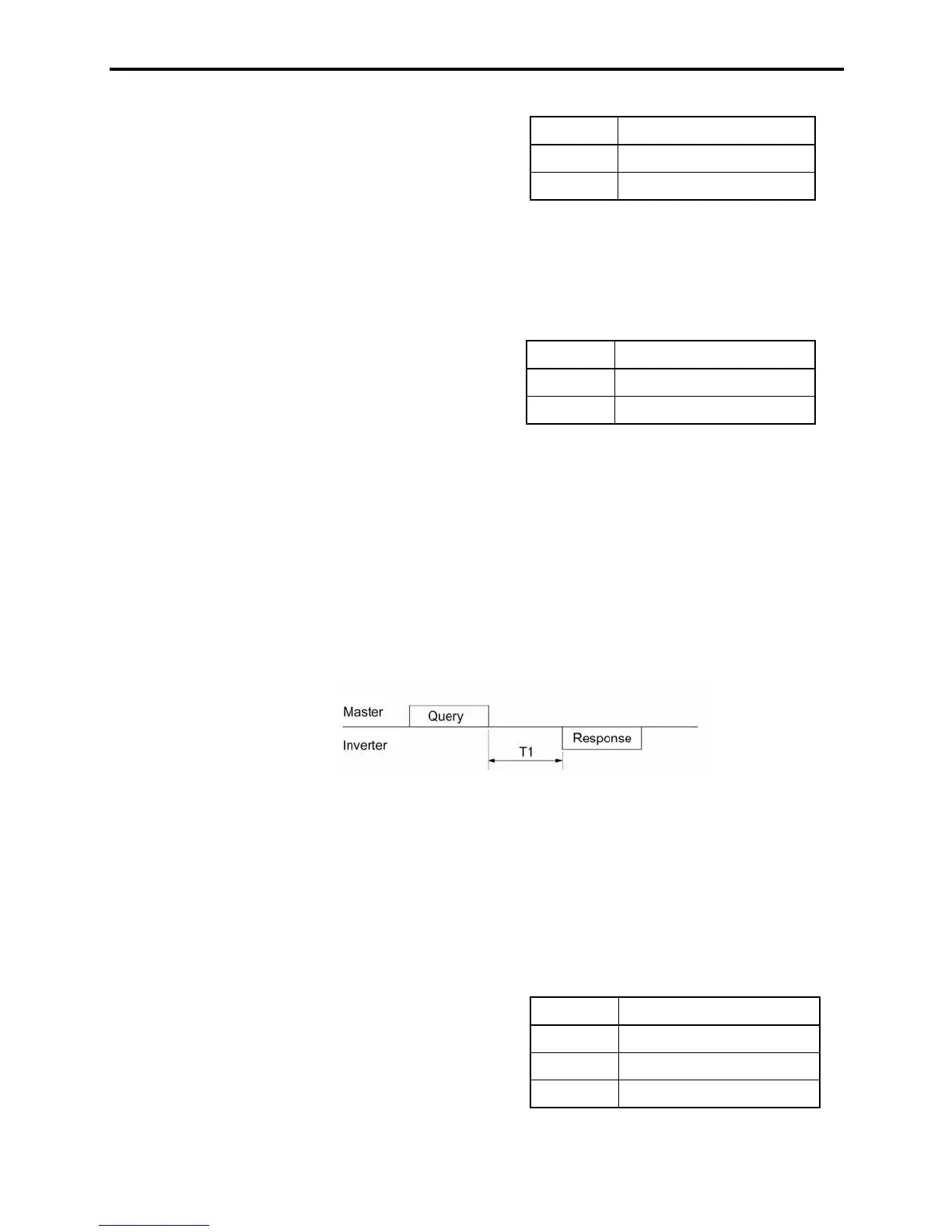
Response latency time (y09)
Sets the latency time from the end of receiving a query sent from the host (such as the PC or
PLC) to the start of sending the response. This function allows using equipment whose response
time is slow for a network requiring quick response.
- Data setting range: 0.00 to 1.00 (sec.)
T1 = Latency time + D
where D is the processing time of the inverter (may vary depending upon the processing status and the run
command in the inverter).
Refer to the RS-485 Communication User's Manual.
- Setting for FRENIC Loader: Set the correct data to the function code depending on the
performance and/or configuration of the PC and protocol converter (such as
RS-485/RS-232C). Note that some protocol converters monitor the communications status
and switch the send/receive of transmission data by timer.
Protocol selection (y10)
Data for y10 Protocol
0 Modbus RTU
1 FRENIC Loader
Selects the communications protocol.
- Setting for FRENIC Loader: Select the
loader protocol (y10 = 1).
2 Fuji general-purpose inverter

 Loading...


