A-10
Table A.2 Continued
No.
Target
device
Phenomena Noise prevention measures
Notes
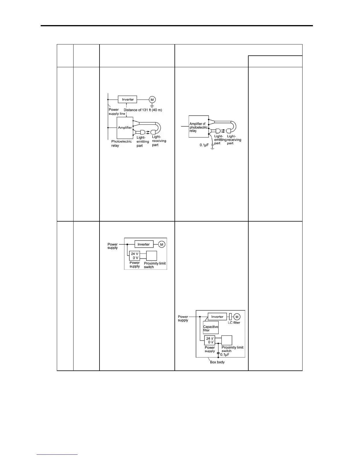
5
Photo-
electric
relay
A photoelectric relay
malfunctioned when the
inverter was operated.
<Possible cause>
Although the inverter and
photoelectric relay are
separated by a sufficient
distance but the power
supplies share a common
connection, it is considered
that conduction noise entered
through the power supply line
into the photoelectric relay.
1) Insert a 0.1 PF capacitor
between the output
common terminal of the
amplifier of the
photoelectric relay and
the frame.
1) If a weak-current
circuit at the
malfunctioning
side is observed,
the measures may
be simple and
economical.
6
Prox-
imity
limit
switch
(electro-
static
type)
A proximity limit switch
malfunctioned.
<Possible cause>
It is considered that the
capacitance type proximity
limit switch is susceptible to
conduction and radiation
noise because of its low noise
immunity.
1) Install an LC filter at the
output side of the
inverter.
2) Install a capacitive filter
at the input side of the
inverter.
3) Ground the 0 V
(common) line of the DC
power supply of the
proximity limit switch
through a capacitor to the
box body of the machine.
1) Noise generated
in the inverter
can be reduced.
2) The switch is
superseded by a
proximity limit
switch of
superior noise
immunity (such
as a magnetic
type).

 Loading...


