Glossary
G-1
Glossary
Acceleration time
Period required when an inverter accelerates its
output from 0 Hz to the output frequency.
Related function codes: F03, F07, E10, and H54
Alarm mode
One of the three operation modes supported by the
inverter. If the inverter detects any malfunction,
error, or fault in its operation, it immediately shuts
down or trips the output to the motor and enters this
mode in which corresponding alarm codes are
displayed on the LED monitor.
Alarm output (for any faults)
A mechanical contact output signal that is generated
when the inverter is halted by an alarm, by
short-circuiting between terminals [30A] and [30C].
Related function code: E27
See Alarm mode.
Analog input
An external voltage or current input signal to give
the inverter the frequency command. The analog
voltage is applied on the terminal [11], the current on
the [C1]. These terminals are also used to input the
signal from the external potentiometer, PTC and PID
feedback signals depending on the function code
definition.
Related function codes: F01, C30, E60 to E62 and
J02
Analog output
An analog DC output signal of the monitored data
such as the output frequency, the current and voltage
inside an inverter. The signal drive an analog meter
installed outside the inverter for indicating the
current inverter running status.
Refer to Chapter 8, Section 8.4.1 "Terminal
functions."
Applicable motor rating
Rated output (in kW) of a general-purpose motor that
is used as a standard motor listed in tables in Chapter
6, "SELECTING PERIPHERAL EQUIPMENT"
and Chapter 8, "SPECIFICA-
TIONS."
Automatic deceleration
A control mode in which deceleration time is
automatically extended up to 3 times of the
commanded time to prevent the inverter from
tripping due to an overvoltage caused by
regenerative power even if a braking resistor is used.
Related function code: H69
Automatic energy saving operation
Energy saving operation that automatically drives
the motor with lower output voltage when the motor
load has been light, for minimizing the product of
voltage and current (electric power).
Related function code: F37
AVR (Automatic Voltage Regulator) control
A control that keeps an output voltage constant
regardless to variations of the input source voltage or
load.
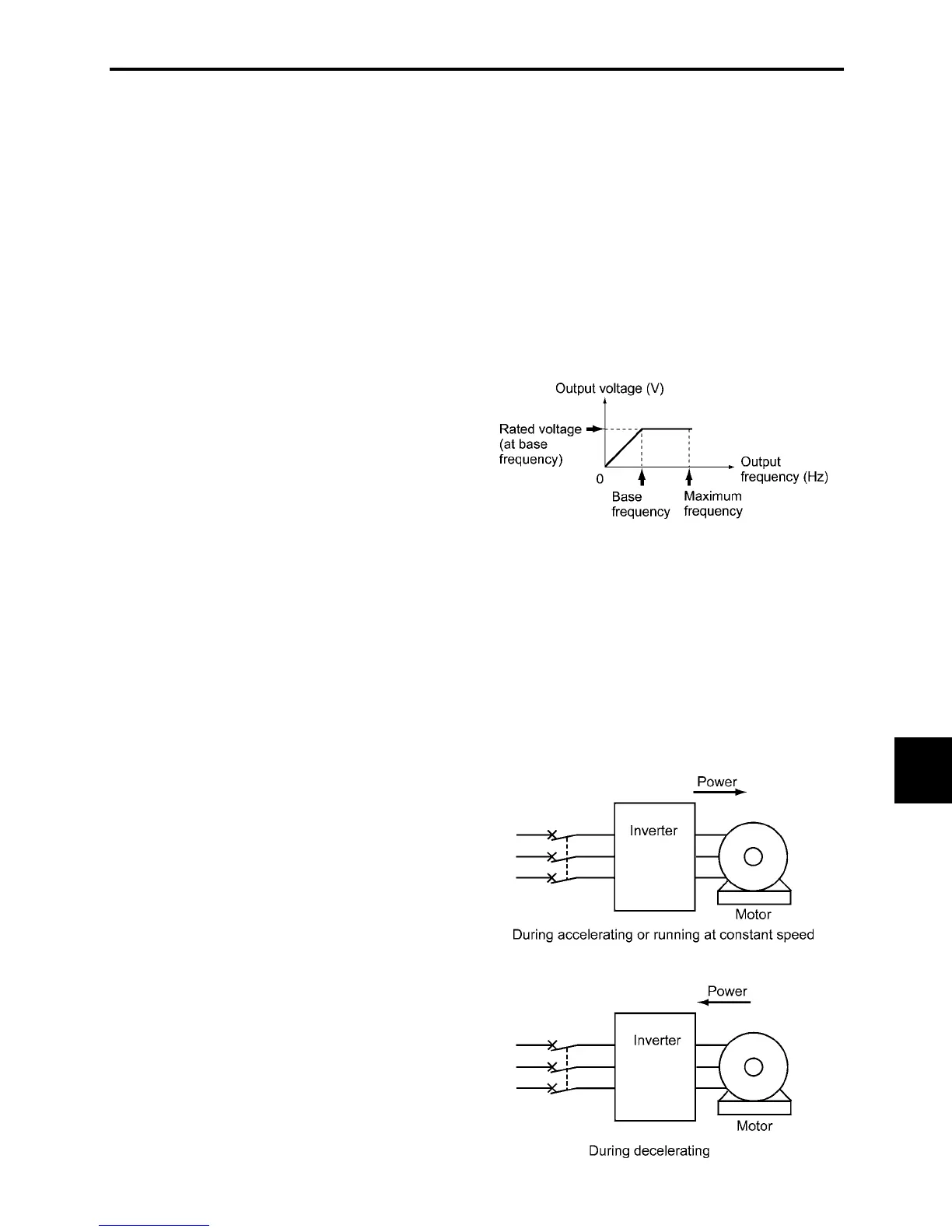
Base frequency
The minimum frequency at which an inverter
delivers a constant voltage in the output V/f pattern.
Related function code: F04
Bias
A value to be added to an analog input frequency to
modify and produce the output frequency.
Related function codes: F18, C50 to C52
Braking torque
Torque that acts in a direction that will stop a rotating
motor (or the force required to stop a running motor).

 Loading...


