3-2
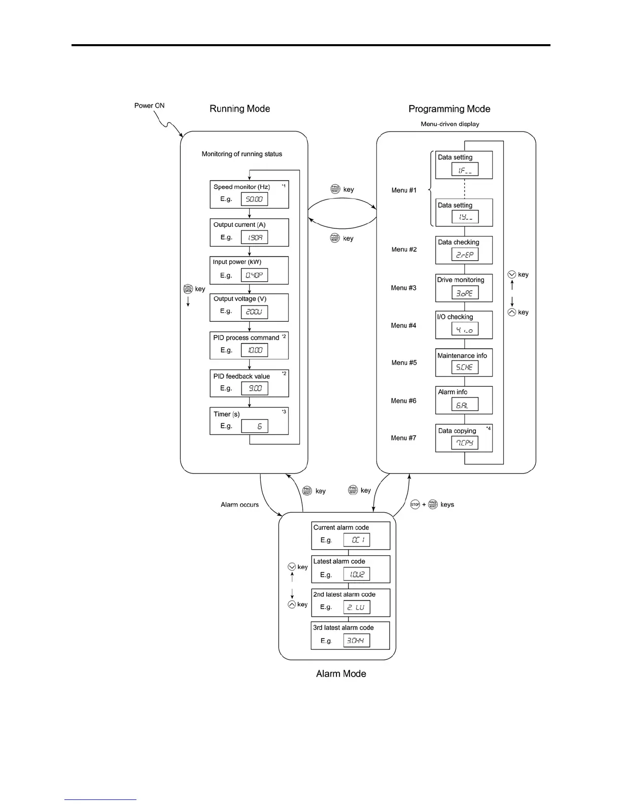
The figure below shows the transition between the running status monitoring screens in Running mode,
that between the menu screens in Programming mode, and that between the alarm code screens in Alarm
mode.
*1 The speed monitor may display the output frequency (Hz), set frequency (Hz), load shaft speed (r/min), line speed
[ft/min. (m/min.)], and constant feeding rate time (min.) which can be selected by setting up function code E48.
*2 These PID-related information will appear only when the inverter is under the PID control. (Refer to Section
3.2.2.)
*3 This will appear only when timer operation is enabled by setting up function code C21. (Refer to Chapter 9,
Section 9.2.3 "C codes (Control functions of frequency).")
*4 This will appear only when the remote keypad (option) is set up for use.
Figure 3.2 Basic Screen Transition in Each Operation Mode

 Loading...


