3-6
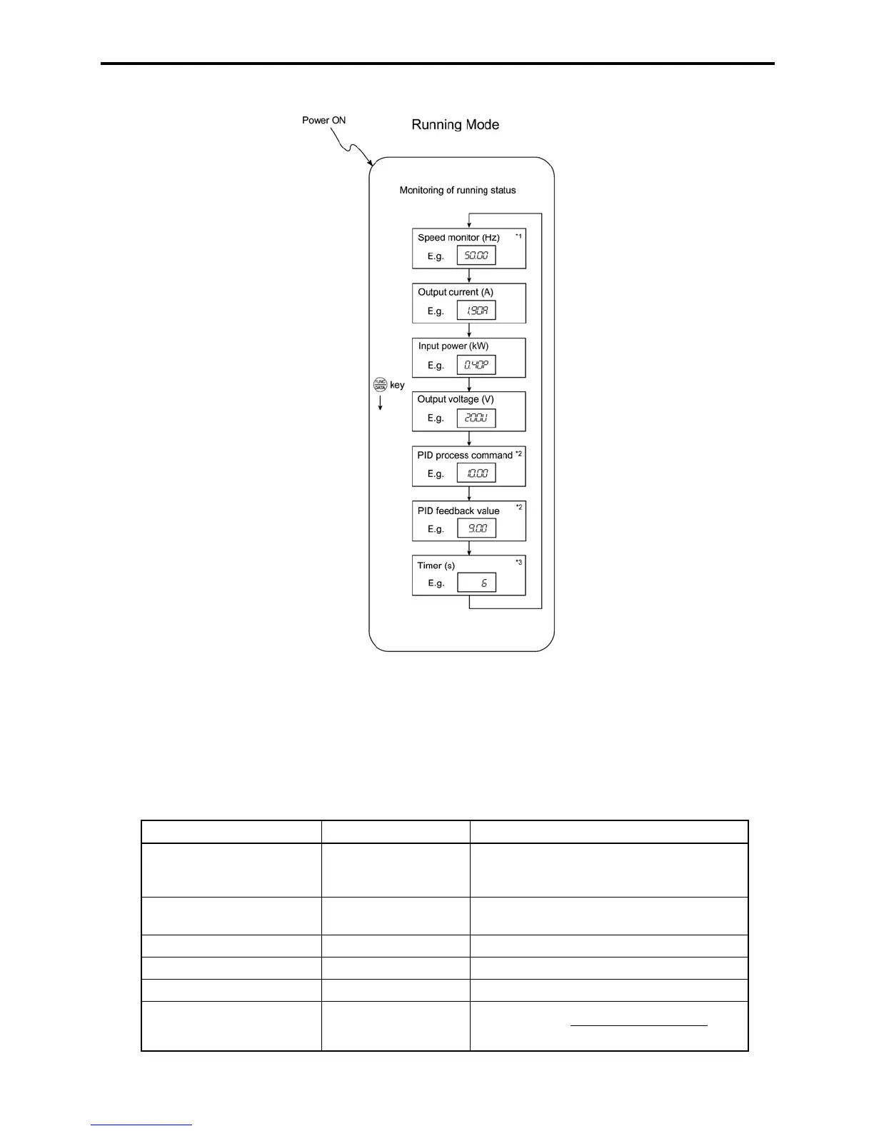
Figure 3.3 shows the procedure example for selecting the desired monitor item.
*1 The speed monitor may display the output frequency (Hz), set frequency (Hz), load shaft speed (r/min), line speed
[ft/min. (m/min.)], and contrast feeding rate time (min.) which can be selected by setting up function code E48.
*2 These PID-related information will appear only when the inverter is under the PID control. (Refer to Section
3.2.2.)
*3 This will appear only when timer operation is enabled by setting up function code C21. (Refer to Chapter 9,
Section 9.2.3 "C codes (Control functions of frequency).")
Figure 3.3 Monitor Item Selection Example
Table 3.2 lists the display items for the speed monitor that can be chosen with function code E48.
Table 3.2 Display Items on the Speed Monitor
Speed monitor items Function code E48 data Meaning of Displayed Value
Output frequency (before slip
compensation) (Hz)
(Factory default)
0 Pre-slip compensation frequency
Output frequency (after slip
compensation) (Hz)
1 Frequency actually being outputted
Set frequency (Hz) 2 Final set frequency
Load shaft speed (r/min) 4 Display value = Output frequency (Hz) x E50
*
Line speed [ft/min (m/min)] 5 Display value = Output frequency (Hz) x E50
*
Constant feeding rate time
(min)
6
Display value =
E39frequencyOutput
E50
u
*
*
Output frequencies contained in these formulas are output frequencies before slip compensation.

 Loading...


