3.3 Programming Mode
3-23
Chap. 3 OPERATION USING THE KEYPAD
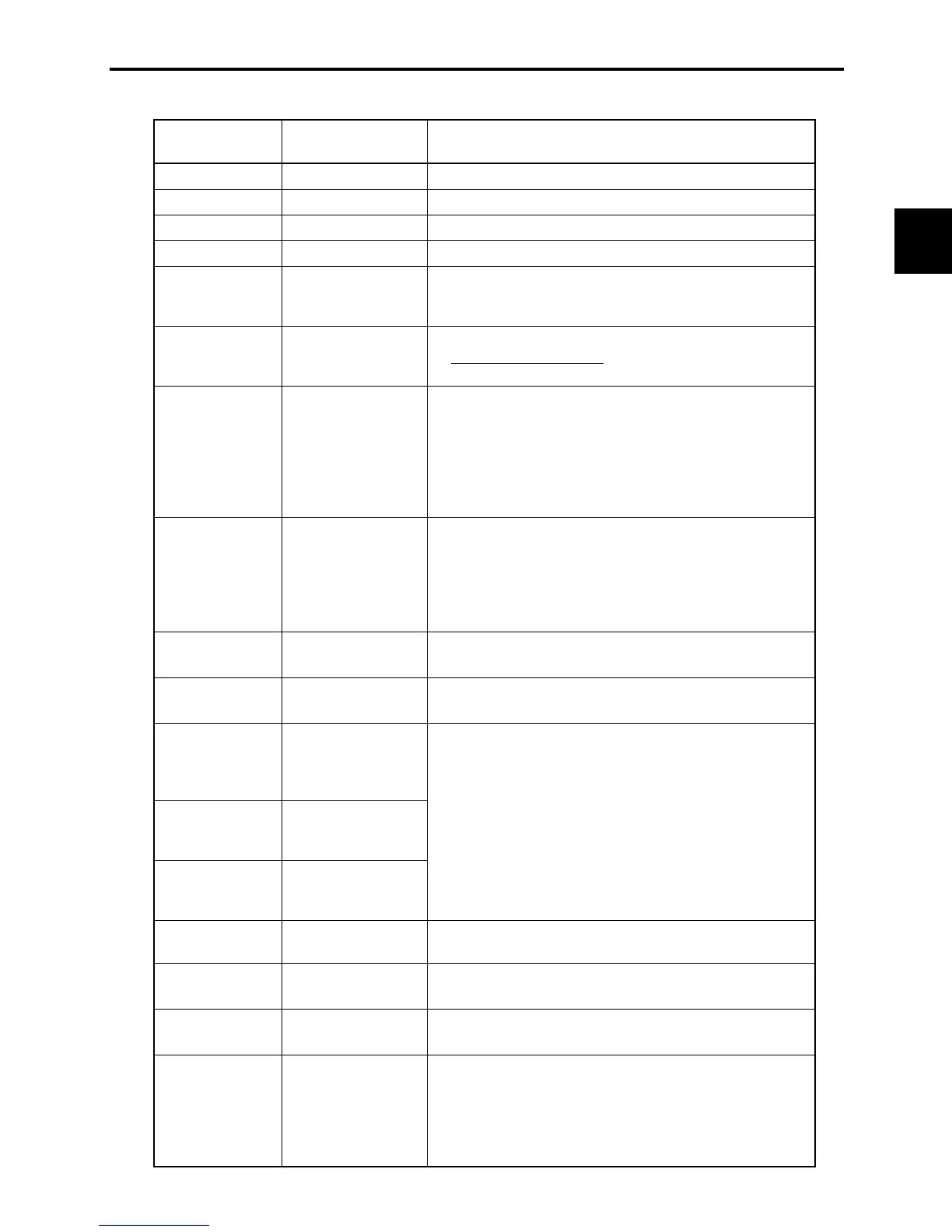
Table 3.13 Alarm Information Contents
LED monitor
shows:
(Item No.)
Display contents Description
A
Output frequency Output frequency before slip compensation
A
Output current Present output current
A
Output voltage Present output voltage
A
Set frequency Present set frequency
A
Rotational direction This shows the rotational direction of a run command being
output.
H
: forward;
T
: reverse; –
–
–
–: stop
A
Running status This shows the running status as a hexadecimal display. Refer
to Displaying running status
in Section 3.3.3 "Monitoring the
running status."
A
Accumulated
running time
Shows the cumulative power-ON time of the inverter.
Unit: thousands of hours. When the total ON time is less than
10,000 hours (display: 0.001 to 9.999), it is possible to check
data in hourly units. When the total time is 10,000 hours or
more (display: 10.00 to 65.53), the display will change to units
of 10 hours. When the total time exceeds 65,535 hours, the
display returns to 0 and the count will start again.
A
No. of startups The motor run times (the number of times the inverter run
command is set to ON) are calculated and displayed.
1.000 indicates 1,000 times. When any number from 0.001 to
9.999 is displayed, the display increases by 0.001 per startup,
and when any number from 10.00 to 65.53 is displayed, the
display increases by 0.01 every 10 startups.
A
DC link bus voltage Shows the DC link bus voltage of the inverter's main circuit.
Unit: V (volts)
A
Max. temperature of
heat sink
Shows the maximum temperature of the heat sink.
Unit: ºC
A
Terminal I/O signal
status (displayed
with the ON/OFF of
LED segments)
A
Terminal input signal
status (in
hexadecimal format)
A
Terminal output
signal status (in
hexadecimal display)
Shows the ON/OFF status of the digital I/O terminals. Refer to
Section 3.3.4 "[1] Displaying control I/O signal terminals" for
details.
A
No. of consecutive
occurrences
This is the number of times the same alarm has occurred
consecutively.
A
Overlapping alarm 1 Simultaneously occurring alarm codes (1)
(
–
–
–
– is displayed if no alarms have occurred.)
A
Overlapping alarm 2 Simultaneously occurring alarm codes (2)
(
–
–
–
– is displayed if no alarms have occurred.)
A
Terminal I/O signal
status under
communication
control (displayed
with the ON/OFF of
LED segments)
Shows the ON/OFF status of the digital I/O terminals under
communication control. Refer to Section 3.3.4 "[2]
Displaying
control I/O signal terminals under communication control
"
for details.

 Loading...


