Chapter 2 Installation and Connection
IP-9500e
22
2.3.2 Decoder
For audio and video decoding, there are two digital vide, one analog video, one digital audio and
two analog audio terminals to connect and audio and video input device.
Digital video output
Connect to SDI OUT on the rear panel of IP-9500e using coaxial cable with BNC connector
and output HD-SDI signal.
Analog video output
Connect to ANALOG VIDEO OUT on the rear panel of IP-9500e using coaxial cable with
BNC connector and output NTSC or PAL signal.
Digital audio output
The HD-SDI embedded audio is supported.
Analog audio output
Connect to ANALOG AUDIO OUT (L), (R) on the rear panel of IP-9500e using the cable
with XLR connector. The impedance is 600Ω balanced. Inputting a signal outside the rated
value will cause a problem in terms of audio level and noise. To output mono signals,
connect the audio device to the AUDIO OUT (L) terminal.
In addition, the synchronization input is available. Connect to GENLOCK IN on the rear panel
of IP-9500e using the coaxial cable with BNC connector. The signal is terminated in 75Ω.
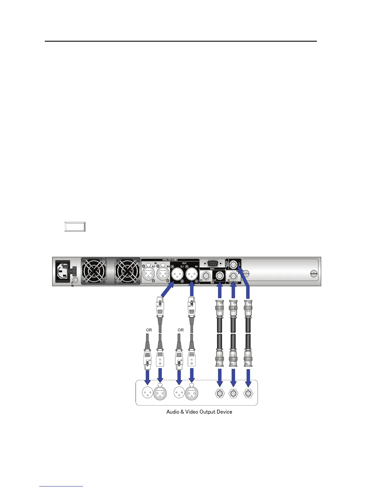
The figure below shows how to connect the digital and analog audio/video and the reference clock
cables. See the next page for the connection of HDMI and voice communication cables.
For details about connectors and cables, see Section 4.2, “Cable and Connector Details.”
For electrical specifications, see Appendix 2.3, “Function Specifications.”
Figure Audio and video input device connections
NOTE: