Chapter 5 Troubleshooting
IP-9500e
65
5.2 Alarm LED Lamp Is On
This section describes corrective actions to take if an alarm LED turns on.
The appropriate corrective action depends on the alarm code displayed. See the table below for this
information.
Reference
See Section 3.3.2, “Log,” for information how to check the alarm log check and an
example with displayed information.
Table 5.2 Alarm codes and corrective actions
Code Corrective action
Lxxx Check the network and destination device. If an error cannot be identified, contact your
system administrator.
Exxx Turn off and on the device. If the device is still operating abnormally after being powered on
again, contact your maintenance personnel. Then, he/she may ask the alarm code.
Ixxx This indicates a loss of video input. Check the video output device and video cable connected
to the video input terminal.
xxx: Indicates a three-digit numeric value. See Section 3.3.2, “Log,” for more details.
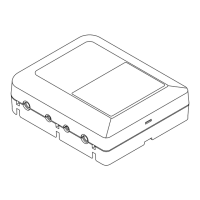
In addition, LED display details are given in the following table:
Table 5.3 LED display details
Display Description
PWR Lights in green when the device is powered on.
RDY
Blinks in green in the operation preparation state, and lights in green in the operation state.
Blinks in orange in the maintenance mode waiting state, and lights in yellow in maintenance
mode.
INDWN
No LED lights in normal state. Lights in orange in the state of audio/video input down or
abnormal.
Blinks in orange when the input signal slipping for encoder and the reference clock input down
for decoder.
ALM
Alarm LED. Blinks or lights in red when a device alarm occurs.
For more details of the alarm log, see Section 3.2.2, “Log” and Section 3.2.7, “Log” of
IP-9500e Software User’s Guide.”
5.2