For more information regarding connector type and part numbers see Power Connector Part Numbers, pg 172. The
power specifications for the controller are provided in Power Requirements, pg 165 and the power specifications
for each amplifier are found under their specific section in the appendix, see Integrated Components, pg 183.
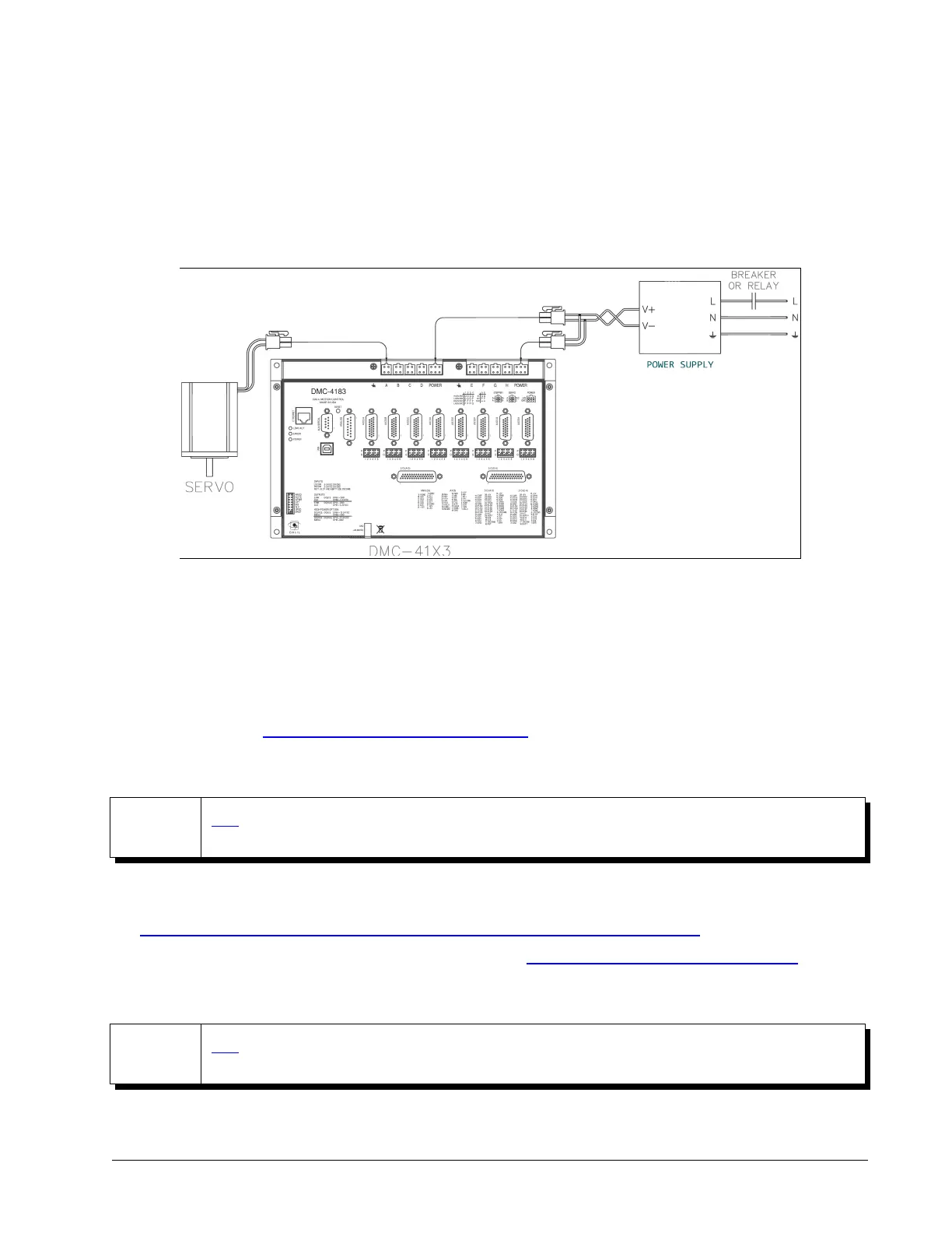
Any emergency stop or disconnect switches should be installed on the AC input to the DC power supply. Relays
and/or other switches should not be installed on the DC line between the Galil and the Power supply. An example
system is shown in Figure 2.1 with a DMC-4183-D3040-D3040:
The green power light indicator should go on when power is applied.
Step 4. Install the Communications Software
After applying power to the controller, a PC is used for programming. Galil's development software enables
communication between the controller and the host device. The current version of Galil's development software
can be found here: http://galil.com/downloads/software/gdk
Step 5. Establish Communications with Galil Software
NOTE
GDK's Step-By-Step tool provides an interactive and easy to follow guide to setting up a Windows PC
for communication with Galil controllers.
GDK will automatically setup the computer for serial communication. For Ethernet communication, see this video
for how to configure your NIC card using Windows to connect to a DMC controller:
http://galil.com/learn/online-videos/basics-galil-design-kit-manager-terminal-and-editor
See the GDK manual for using the software to communicate: http://galil.com/sw/pub/all/doc/gdk/man/
Step 6. Motor Setup with GDK Step-By-Step
NOTE
GDK's Step-By-Step tool provides an interactive guide for the automatic set up of brushed, brushless,
and stepper motors when using internal amplifiers.
For manual setup instructions, refer to the specific amplifier appendix section which were listed in Table 2.3.
Chapter 2 Getting Started ▫ 17 DMC-41x3 User Manual
Figure 2.1: Wiring for DMC-4183 with Amplifiers