Step 1. Connecting Encoder Feedback
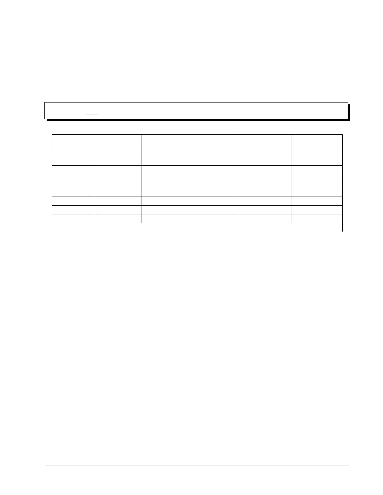
The type of feedback the controller is capable of interfacing with depends on the additional options ordered for
the controller. Table 2.1 shows the different encoder feedback types available for the DMC-41x3 including which
options are required. Note that each feedback type has a different configuration command. See the Command
Reference for full details on how to properly configure each axis.
NOTE
GDK's Step-By-Step tool provides an interactive walk-through for configuring motor encoders.
Feedback Type
Configuration
Command
ICM/Part Number Required Connection Location Firmware Required
Standard
Quadrature
CE
Standard on all units Encoder Standard
Pulse and
Direction
CE
Standard on all units Encoder Standard
Analog
1
AF
Standard on all units
(12-bit Standard. 16-bit optional)
Analog Standard
SSI
SI
SER option Encoder -SER
BiSS
SS
SER option Encoder -SER
None
2
– – – –
Other Contact Galil
Table 2.1: Configuration commands, ICM/Part numbers required for a given feedback type
1
All wiring/electrical information regarding using analog inputs can be found in Analog Inputs, pg 32.
2
Although stepper systems do not require feedback, Galil supports a feedback sensor on each stepper axis. Servo motors require a
position sensor.
Different feedback types can be used on the same controller. For instance, one axis could be using standard
quadrature and the next could be using SSI. By default, all axes are configured for standard quadrature.
When a stepper motor is used, the auxiliary encoder for the corresponding axis is unavailable for an external
connection. If an encoder is used for position feedback with a stepper motor, connect the encoder to the main
encoder input corresponding to that axis. The commanded position of the stepper can be interrogated with TD
and the encoder position can be interrogated with TP.
See SER – BiSS and SSI Absolute Encoder Interface, pg 170 for pin-outs and electrical information for SSI and BiSS
options.
Encoder pin-outs can be found here:
Jn1 - Encoder 26 pin HD D-Sub Connector (Female), pg 176
Chapter 2 Getting Started ▫ 13 DMC-41x3 User Manual
 Loading...