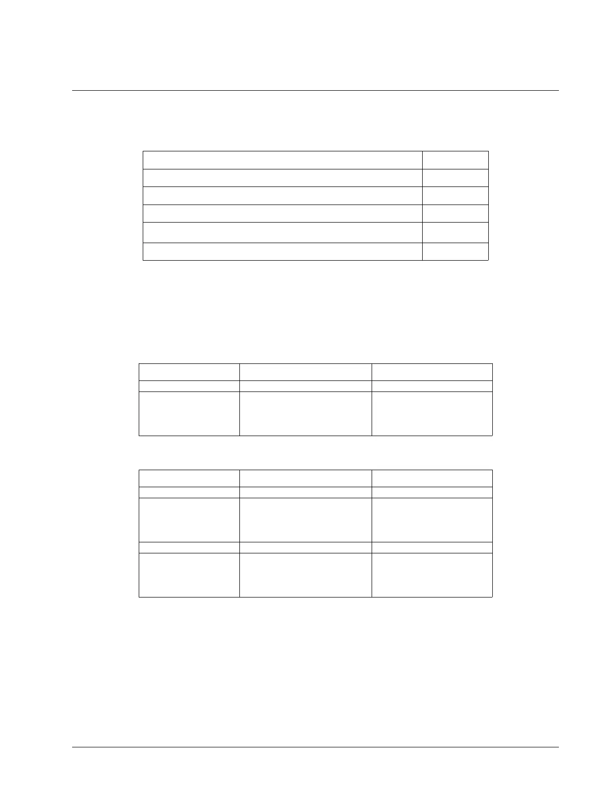
Optoisolated Input Electrical Information
Electrical Specifications
INCOM/LSCOM Max Voltage 24 V
DC
INCOM/LSCOM Min Voltage 0 V
DC
Minimum current to turn on Inputs 1.2 mA
Minimum current to turn off Inputs once activated (hysteresis) 0.5 mA
Maximum current per input
1
11 mA
Internal resistance of inputs 2.2 kΩ
1
See the Input Current Limitations section on pg. 174 for more details.
The DMC-41x3's optoisolated inputs are rated to operate with a supply voltage of 5-24 VDC. The optoisolated
inputs are powered in banks. For example, INCOM (Bank 0), located on the 44-pin I/O (A-D) D-sub connector,
provides power to DI[8:1] (digital inputs), the abort input (ABRT), reset (RST), and electric lock-out (ELO). Table 3.1
shows all the input banks power commons and their corresponding inputs for 1-4 axis controllers and Table 3.2
shows the input banks for 5-8 axis controllers.
Common Signal Common Signal Location Powers Inputs Labeled
INCOM (Bank 0) I/O (A-D) D-Sub Connector DI[8:1], ABRT, RST, ELO
LSCOM (Bank 0) I/O (A-D) D-Sub Connector FLSA, RLSA, HOMA
FLSB, RLSB, HOMB
FLSC, RLSC, HOMC
FLSD, RLSD, HOMD
Table 3.1: 1-4 axis controller INCOM and LSCOM banks and corresponding inputs powered
Common Signal Common Signal Location Powers Inputs
INCOM (Bank 0) I/O (A-D) D-Sub Connector DI[8:1], ABRT, RST, ELO
LSCOM (Bank 0) I/O (A-D) D-Sub Connector FLSA, RLSA, HOMA
FLSB, RLSB, HOMB
FLSC, RLSC, HOMC
FLSD, RLSD, HOMD
INCOM (Bank 1) I/O (E-H) D-Sub Connector DI[16:9]
LSCOM (Bank 1) I/O (E-H) D-Sub Connector FLSE, RLSE, HOME
FLSF, RLSF, HOMF
FLSG, RLSG, HOMG
FLSH, RLSH, HOMH
Table 3.2: 5-8 axis controller INCOM and LSCOM banks and corresponding inputs powered
The full pin-outs for each bank can be found in the Pin-outs, pg 175.
Chapter 3 Connecting Hardware ▫ 23 DMC-41x3 User Manual