7 Protection Parameter Settings
This setting determines the enabling/disabling of blocking second stage overcurrent element due to presence of inrush current.
If I>2 Blocking and 2nd Harmonic settings are enabled, then (I>2) trip command will be blocked in case 2nd harmonics content in any
phase is above the 2ndHarm Thresh. and fundamental current is below I> lift 2H setting . (Set in SYSTEM CONFIG Menu.)
2.12.2.3 I>3 Function
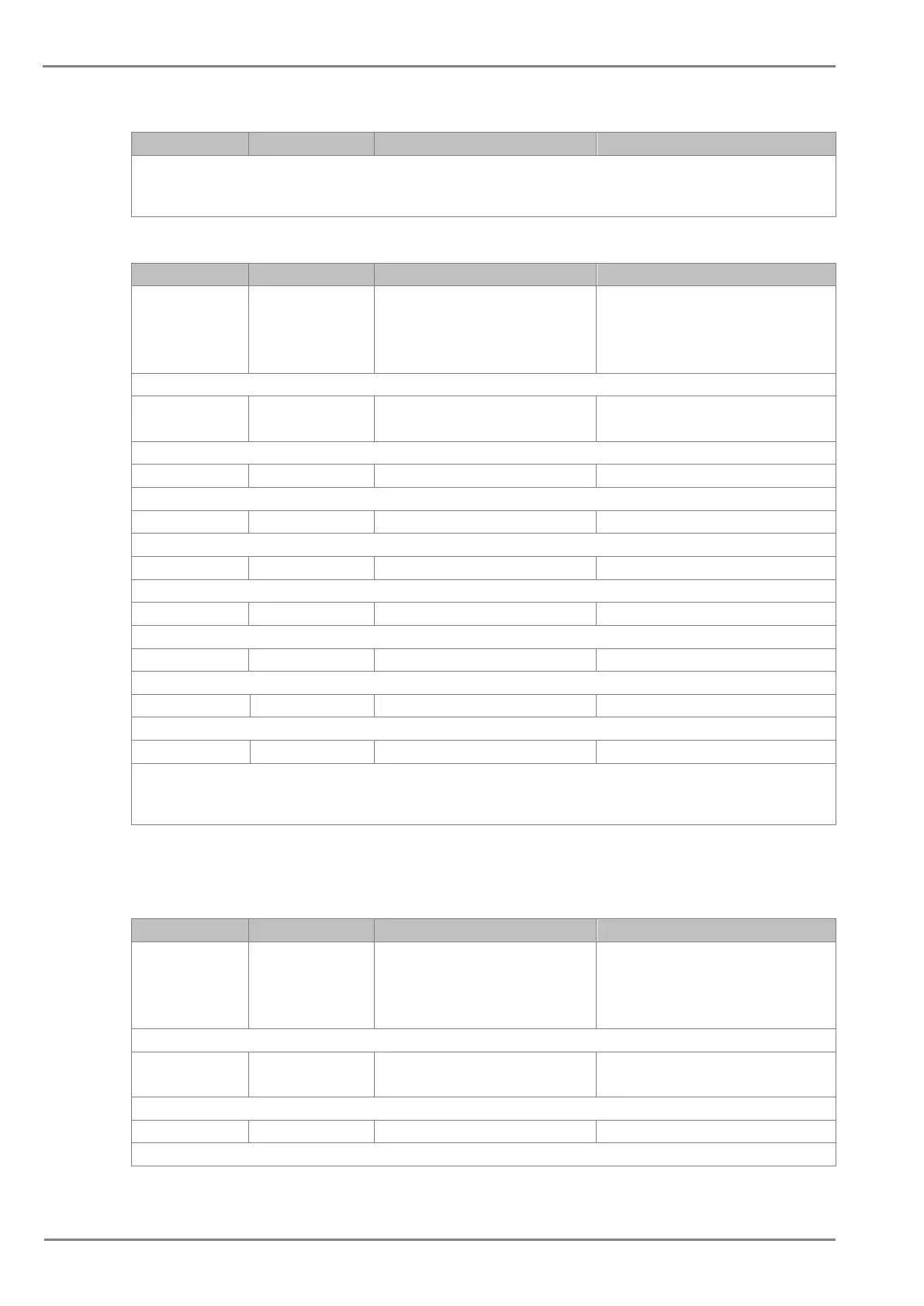
Sr. No Parameter Default setting Setting Range
1. I>3 Function IEC S Inverse
Disabled / DT / IEC S Inverse / S Inverse
1.3Sec / IEC V Inverse / IEC E Inverse / UK
LT Inverse / IEEE M Inverse / IEEE V Inverse
/ IEEE E Inverse / US Inverse / US ST
Inverse
This setting determines the tripping characteristic for the third stage overcurrent element.
2. I>3 Current Set 1.00*In
If DT 1.0 to 35.00*In step 0.01*In
If IDMT 0.05 to 4.00*In step 0.01*In
This setting determines the pick-up setting for second third overcurrent element.
3. I>3 Time Delay 1.00 S 0s to 100s step 0.01s
This setting determines the time-delay for the definite time setting if selected for third stage overcurrent element.
4. I>3 TMS 1.000 0.025 to 1.2 step 0.005
This time multiplier setting is used to adjust the operating time of the IEC / UK IDMT characteristic.
This time multiplier setting is used to adjust the operating time of the IEEE / US IDMT curves.
6. I>3 Reset Char DT DT/IDMT
This setting determines the type of reset/release characteristics. IDMT applicable for IEEE curves only.
7. I>3 RTMS 1.000 0.025 to 1.2 step 0.005
This setting determines the reset/release time for IEEE IDMT characteristic
This setting determines the reset/release time for Definite Time (DT) and all IDMT curve
9. I>3 2H Blocking Disabled Enabled / Disabled
This setting determines the enabling/disabling of blocking third stage overcurrent element due to presence of inrush current.
If I>3 Blocking and 2nd Harmonic settings are enabled, then (I>3) trip command will be blocked in case 2nd harmonics content in any
phase is above the 2ndHarm Thresh. and fundamental current is below I> lift 2H setting . (Set in SYSTEM CONFIG Menu.)
2.12.3 EARTH FAULT 1 (Measured)
2.12.3.1 IN1>1 Function
Sr. No Parameter Default setting Setting Range
1. IN1>1 Function IEC S Inverse
Disabled / DT / IEC S Inverse / S Inverse
(1.3Sec) / IEC V Inverse / IEC E Inverse / UK
LT Inverse / IEEE M Inverse / IEEE V Inverse
/ IEEE E Inverse / US Inverse / US ST
Inverse
This setting determines the tripping characteristic for the first stage measured earth fault element.
2. IN1>1 Current Set 1.00*In
If DT 0.05 to 35.00*In step 0.01*In
If IDMT 0.05 to 4.00*In step 0.01*In
This setting determines the pick-up setting for first stage measured earth fault element.
3. IN1>1 Time Delay 1.00 S 0s to 200s step 0.01s
This setting determines the time-delay for the definite time setting if selected for first stage of measured earth fault element.

 Loading...


