EasyManua.ls Logo

GE Agile P50 Series User Manual

GE Agile P50 Series
268 pages
To Next Page IconTo Next Page
To Previous Page IconTo Previous Page
Page #23 background image
P50 Agile P153
3 Hardware Design
P153/EN M/B
3-1
HARDWARE DESIGN
CHAPTER 3

Table of Contents

Question and Answer IconNeed help?

Do you have a question about the GE Agile P50 Series and is the answer not in the manual?

GE Agile P50 Series Specifications

General IconGeneral
BrandGE
ModelAgile P50 Series
CategoryRelays
LanguageEnglish

Summary

Introduction

2 Introduction

Overview of the relay's purpose and capabilities.

2.1 Features

Describes the relay's core features and functionalities.

2.1.1 Protection & Control

Details the timed and instantaneous phase and earth fault protection features.

2.1.2 Measurement, Recording & Post Fault Analysis

Covers metering, recording fault data, and analysis capabilities.

2.1.3 Front Panel Interface

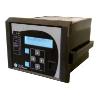
Describes the LCD display, LEDs, and navigation keys on the device.

2.1.4 Communications

Details the USB and RS485 ports and supported protocols.

2.2 Functional Overview

Lists the protection functions supported by the P153 relay.

2.3 Ordering Information

Provides details on available variants and how to order the P153 relay.

Safety Information

1 HEALTH AND SAFETY

Emphasizes the need for qualified personnel and adherence to safety practices.

2 SYMBOLS

Explains cautionary and warning symbols used in the manual and on equipment.

3 INSTALLATION, COMMISSIONING AND SERVICING

Covers hazards related to lifting, electrical work, and general installation safety.

3.3 FUSING REQUIREMENTS

Specifies requirements for protecting digital input and CT circuits.

3.4 EQUIPMENT CONNECTIONS

Provides safety guidelines for connecting terminals and wiring.

3.5 PROTECTION CLASS 1 EQUIPMENT REQUIREMENTS

Details requirements for earthing Class 1 equipment.

3.6 PRE-ENERGISATION CHECKLIST

Lists essential checks before energizing the equipment.

3.7 PERIPHERAL CIRCUITRY

Discusses safety precautions for CT secondary circuits and external components.

3.8 UPGRADING/SERVICING

Safety warnings for module insertion/removal and internal handling.

4 DECOMMISSIONING AND DISPOSAL

Safety instructions for isolating power and proper disposal procedures.

5 REGULATORY COMPLIANCE

Information on EMC and LVD compliance directives.

Hardware Design

2 Hardware Design

Outlines the main components of the P153 hardware.

2.1 Overview of Hardware design

Explains the hardware design with internal CTs, SMPS, and signal processing.

2.2 Microcontroller with DSP module

Describes the 32-bit controller and its features.

2.2.1 Microcontroller module (Processor board) features

Lists the specifications of the microcontroller module.

2.3 Microcontroller and analog measurement

Details the analog input processing and CT signal scaling.

2.4 Digital input /output module

Describes the DI and DO channels and their isolation.

2.5 Power supply module

Explains the PWM switching mode power supply unit.

2.6 Communication module

Covers the USB and RS485 ports for communication.

2.7 Human machine interface module

Describes the LCD, touch keys, and LEDs on the front panel.

Front Panel

2 FRONT PANEL

Details the components and layout of the device's front panel.

2.1 User Interface

Explains how to interact with the device using the front panel.

2.1.1 LCD Display

Describes the 16x2 character backlit LCD display.

2.1.2 Touch Keys

Details the function of navigation and control keys.

2.1.3 LEDs

Explains the purpose of the six high-intensity LEDs.

2.1.4 RS 485 Port

Describes the rear RS485 port for SCADA connectivity.

2.1.5 USB Port

Details the front USB port for PC communication.

Configuration

2 Configuration

Outlines the common methodology for setting device parameters.

2.1 Changing the Settings

Step-by-step guide to modifying device settings.

2.2 Password Entry

Explains how to access and change the device password.

2.3 Menus

Overview of the device's menu structure.

2.3.1 Default Display

Describes the initial display after power-on or reset.

2.3.2 Main Menu Contents

Lists the primary menu options available on the device.

2.3.3 System Data Menu

Accesses settings like language, serial number, and frequency.

2.3.4 View Records Menu

Provides access to fault, event, maintenance, and alarm records.

2.3.5 Measurement Menu

Displays measured electrical quantities like currents and thermal state.

2.3.6 CB Control Menu

Settings related to circuit breaker control and supervision.

2.3.7 Date and Time Menu

Settings for configuring date, time, and daylight saving.

2.3.8 Configuration Menu

Settings for restoring defaults, copying groups, and enabling system features.

2.3.9 Transformer Ratios Menu

Configuration of CT primary and secondary ratios.

2.3.10 Record Control Menu

Settings for clearing stored records and resetting thermal data.

2.3.11 Communication Menu

Configuration of communication parameters like address and baud rate.

2.3.12 I/O Configuration Menu

Configuration of relays, LEDs, AND logic, and opto inputs.

2.3.13 O/P Relay Configuration Menu

Settings for output relay timing and reset mechanisms.

2.3.14 Disturbance Record Menu

Setting the trigger position for disturbance recording.

2.3.15 Commissioning Test Menu

Accesses test modes, patterns, and LED checks.

2.3.16 Group 1 Menu

Settings specific to Group 1 configuration.

2.3.17 Group 2 Menu

Settings specific to Group 2 configuration.

2.4 Configuration Flowcharts

Illustrates the navigation flow through the configuration menus.

Protection Functions

2 Protection functions

Details the various protection functions offered by the P153 relay.

2.1 Overcurrent Protection Principles

Explains the fundamental principles of overcurrent protection.

2.1.1 IDMT Characteristics

Describes Inverse Definite Minimum Time (IDMT) curves.

2.1.2 Principle of Protection Function Implementation

Explains how protection functions are implemented using IEDs.

2.1.3 Timer Hold Facility/Reset Characteristics

Details the timer hold and reset facilities for protection stages.

2.2 Phase Overcurrent Protection

Covers faults between phases and types of phase faults.

2.2.1 Phase Overcurrent Protection Implementation

Explains the implementation of phase overcurrent protection stages.

2.3 Negative Sequence Overcurrent Protection

Discusses using negative sequence elements for fault detection.

2.3.1 Negative Sequence Overcurrent Protection Implementation

Details the implementation of negative sequence overcurrent protection.

2.3.2 Negative Sequence Overcurrent Protection Logic

Explains the logic for negative sequence overcurrent protection.

2.4 Earth Fault Protection

Covers earth faults and methods for measuring them.

2.4.1 Earth Fault Protection Elements

Describes the elements used for earth fault protection.

2.4.2 Earth Fault Protection Logic

Explains the logic for earth fault protection.

2.5 Thermal Overload Function

Details the thermal overload protection mechanism.

2.5.1 Thermal Overload Protection Implementation

Explains the implementation of thermal overload protection.

2.6 Broken Conductor

Describes detection of faults due to broken conductors.

2.6.1 Broken Conductor Protection Implementation

Details the implementation of broken conductor protection.

2.6.2 Broken Conductor Protection Logic

Explains the logic for broken conductor detection.

2.7 Undercurrent /Loss of Power Protection Function

Functionality for detecting undercurrent or loss of power.

2.8 Circuit Breaker Fail Protection

Protection against circuit breaker failure to operate.

2.8.1 Circuit Breaker Fail Implementation

Details the implementation of circuit breaker fail protection.

2.8.2 Circuit Breaker Fail Logic

Explains the logic for circuit breaker fail detection.

2.9 Cold Load Pickup Function

Manages high currents during load energization to prevent nuisance tripping.

2.9.1 Cold Load Pickup Logic

Explains the logic for cold load pickup functionality.

2.9.2 Cold Load Pickup for SWITCH ONTO FAULT Condition

Handles faults occurring immediately after breaker closure.

2.10 Inrush Current Blocking Function (2ND Harm Blocking)

Blocks tripping during transformer inrush using second harmonic analysis.

2.10.1 Second Harmonic Blocking Implementation

Details the implementation of second harmonic blocking.

Protection Parameter Settings

2 Protection Parameter Settings

Details the configurable parameters for protection functions.

2.1 System Data

Configuration settings for system-level parameters.

2.2 CB CONTROL Settings

Parameters for controlling and supervising circuit breakers.

2.3 DATE AND TIME Settings

Configuration for date, time, and daylight saving.

2.4 CONFIGURATION Settings

Manages overall device configuration and feature enabling.

2.5 TRANS. RATIOS Settings

Settings for transformer current transformer ratios.

2.6 RECORD CONTROL Settings

Options for managing event, fault, and disturbance records.

2.7 COMMUNICATION Settings

Configuration of communication interface parameters.

2.8 IO CONFIGURATION Settings

Configuration of digital inputs, outputs, and logic.

2.9 O/P RELAY CONFIG Settings

Settings for output relay timing and reset mechanisms.

2.10 DISTURBANCE RECORD Settings

Configuration for disturbance recording parameters.

2.11 COMMISSION TEST Settings

Settings for performing device commissioning tests.

2.12 GROUP Settings

Manages protection settings across different groups.

Monitoring & Control

2 Monitoring & Control

Functions for monitoring device status and events.

2.1 Monitoring Functions (Event, Fault, Disturbance Record)

Details on logging and retrieving event, fault, and disturbance data.

2.1.1 Event Record

Describes the generation and storage of event records.

2.1.2 Alarm Record

Information on how alarms are logged and acknowledged.

2.1.3 Fault Record

Details on triggering and analyzing fault records.

2.1.4 Maintenance Record

Describes logs for internal failures and maintenance events.

2.1.5 Disturbance Record

Covers recording and extracting disturbance waveforms.

2.2 Record Control

Settings for clearing stored records and resetting thermal state.

2.3 Display of Measuring Parameters

How to view measured electrical quantities on the LCD.

2.4 Opto Inputs

Configuration and assignment of digital opto-inputs.

2.5 Output Relays

Details on relay outputs and their functions.

2.5.1 Output Relay Function Assignment

Assigning functions to output relays RL1-RL4.

2.5.2 O/P Relay Configuration

Setting self-reset or latching behavior for relay contacts.

2.5.3 O/P Contact Open Time

Timer for holding relay contacts after trip.

2.6 Programmable LEDs

Configuration of bi-colour LEDs for status indication.

2.7 Logic Equations

Using AND logic equations for Boolean functions.

2.8 CB Monitoring

Monitoring circuit breaker operation statistics.

2.8.1 CB Open Supervision

Detects slow CB operation and raises an alarm.

2.8.2 CB Open Operation Alarm

Generates an alarm based on CB operation count.

2.9 CB Control

Options for controlling the circuit breaker locally or remotely.

2.9.1 Local Control using IED Menu

Performing CB operations via the IED menu.

2.9.2 Remote Control

Enabling remote CB control via SCADA or other systems.

2.10 Trip Circuit Supervision

Monitors the trip coil circuit for integrity.

2.10.1 Calculations for External Resistor

Guidance on calculating resistor values for TCS scheme.

2.11 Self-Diagnostic Features

How the relay detects and reports internal hardware/software faults.

2.12 Watchdog Feature

Monitors hardware health and detects faults.

SCADA Communications

2 SCADA COMMUNICATIONS

Details how SCADA communication standards are applied.

2.1 Modbus

Describes the application of the Modbus standard on the Px50 platform.

2.1.1 Overview

Provides an overview of Modbus, including connection and modes.

2.1.2 MODBUS Functions

Lists supported Modbus function codes and protocol mapping.

2.1.2.1 Protocol Mapping

Maps Modbus function codes to register addresses.

2.2 IEC60-870-5-103

Describes the application of the IEC 60870-5-103 standard.

2.2.1 Overview

Overview of the IEC 60870-5-103 standard's application.

2.2.2 Physical Connection and Link Layer

Details connection options for IEC 60870-5-103.

2.2.3 Initialisation

Procedures for initializing communication.

2.2.4 Time Synchronisation

Setting time and date using the synchronization feature.

2.2.5 Spontaneous Events

Categorization of events using function type and information number.

2.2.6 General Interrogation (GI)

Requesting device status and information during GI cycle.

2.2.7 Cyclic Measurements

How measured values are transmitted cyclically.

2.2.8 Commands

Lists supported commands for the P153 relay.

2.2.9 Test Mode

Enabling test mode via front panel menu.

2.2.10 Disturbance Records

Storing and extracting disturbance records.

2.2.11 Configuration

Steps for configuring the IED for the protocol.

2.2.12 Protocol Mapping

Maps information numbers to functions and commands.

Installation

2 Installation

Covers procedures for handling, mounting, and connecting the device.

2.1 Handling the Goods

Requirements for receiving, unpacking, and storing the device.

2.1.1 Receipt of the Goods

Instructions for checking product upon delivery.

2.1.2 Unpacking the Goods

Guidance on careful unpacking and handling components.

2.1.3 Storing the Goods

Proper storage conditions to maintain product integrity.

2.1.4 Dismantling the Goods

Basic precautions for dismantling the device.

2.2 Mounting the Device

Details on flush panel mounting procedures.

2.2.1 Flush Panel Mounting

Step-by-step guide for mounting the relay in a panel.

2.3 Relay Connection

Safety and wiring guidelines for relay connections.

2.3.1.1 Relay Operating Condition

Specifies operating within electrical and environmental limits.

2.3.1.2 Current Transformer (CT) Circuit

Safety warnings for CT secondary circuit connections.

2.3.1.3 Insulation and dielectric strength testing

Procedures for insulation testing and capacitor discharge.

2.3.2 Cables and Connectors

Guidelines on wiring types and connections.

2.3.3 Terminal Blocks

Details on various terminal blocks for connections.

2.3.3.1 CT connections

Instructions for terminating CT wires with ring lugs.

2.3.3.2 Input / Output connections

Wiring specifications for digital input/output terminals.

2.3.3.3 Rear Serial Port connection

Details on connecting the rear serial port for SCADA.

2.3.3.4 Power Supply Connections

Guidelines for wiring auxiliary supply inputs.

2.3.3.5 Earth Connection

Instructions for connecting the relay to the earthing bar.

2.3.3.6 Current Transformers

Wiring specifications for current transformer connections.

2.3.3.7 EIA(RS) 485 Connections

Cable specifications for EIA (RS485) connections.

2.3.3.8 Output Relay Connections

Wiring instructions for output relay connections.

2.3.3.9 USB Connection

Details on connecting a PC to the IED via USB.

2.4 Case dimensions

Provides the physical dimensions and panel cutout details.

Commissioning Instructions

2 Commissioning

Outlines the procedures for testing and commissioning the relay.

2.1 Commissioning Test Menu

Describes the test facilities available in the IED.

2.1.1 Test Mode

How to enable test mode for secondary injection and output testing.

2.1.2 Test Pattern

Selecting output relay contacts for testing.

2.1.3 Contact Test

Procedure for testing relay contact state changes.

2.1.4 Test LEDs

Testing the functionality of the programmable LEDs.

2.1.5 Opto Input status check

Monitoring the status of opto-inputs.

2.1.6 Opto Output status check

Monitoring the status of relay outputs.

2.1.7 Commissioning Test equipment required

Lists the minimum test equipment needed for commissioning.

2.1.8 Battery check

Steps for checking and replacing the internal battery.

2.1.9 External circuitry check

Verifying external wiring, CTs, and auxiliary supply.

2.1.9.1 Earthing

Ensuring proper connection to the earthing terminal.

2.1.9.2 CT Polarity

Verifying correct CT connection and polarity.

2.1.10 Check relay settings

Verifying application-specific settings are correctly applied.

2.1.11 Protection Timing checks

Verifying the timing accuracy of protection functions.

2.1.11.1 Overcurrent check

Testing the operating time of the overcurrent protection stage.

2.1.11.2 Connecting the Test circuit

Steps for connecting the test circuit for overcurrent checks.

2.1.11.3 Performing the Test

Procedure for executing the overcurrent protection test.

2.1.11.4 Checking the Operating time

Verifying the operating time against specified ranges.

2.1.12 Onload checks

Performing checks while the plant is energized.

2.1.12.1 Onload checks

Measuring secondary current values and comparing them.

2.1.13 Final check

Final steps to restore the device to service after testing.

Maintenance and Troubleshooting

2 MAINTENANCE

Procedures for routine maintenance and checks.

2.1 Maintenance checks

Regular checks to ensure correct operation and wiring integrity.

2.1.1 Opto-Isolators

Checking opto-input functionality using commissioning tests.

2.1.2 Output Relays

Checking output relay functionality using commissioning tests.

2.1.3 Measurement Accuracy

Verifying measured values against known system or injected values.

2.2 Changing the Battery

Instructions for replacing the internal battery.

2.2.1 Replacing the Lithium Coin Battery

Step-by-step guide for replacing the coin battery.

2.3 Replacing the Unit

Procedure for replacing a faulty unit and re-commissioning.

2.4 Cleaning

Guidelines for cleaning the IED using a lint-free cloth.

3 Troubleshooting

Diagnosing and resolving hardware and software faults.

Technical Specifications

2 TECHNICAL SPECIFICATION

Detailed technical specifications of the P153 relay.

Current Input

Specifications for CT secondary, burden, and withstand capacity.

Auxiliary Supply

Details on nominal voltage, operating range, and burden.

Opto Isolated Input

Specifications for opto-isolated input voltage and burden.

Output Contact

Specifications for non-latching output contacts.

Accuracy of protection function

Accuracy tolerances for overcurrent and earth fault functions.

Overcurrent

Operating value, time, and reset specifications for overcurrent.

Earth Fault 1 (Measured)-Standard CT / SEF CT

Specifications for measured earth fault protection.

Earth Fault 2 (Derived)

Specifications for derived earth fault protection.

Negative Phase Sequence Overcurrent

Operating value, time, and reset for negative sequence overcurrent.

Broken Conductor

Operating value specifications for broken conductor detection.

2nd Harmonic

Specifications for second harmonic blocking thresholds.

Thermal Overload

Operating time specifications for thermal overload.

Under current

Operating value and time specifications for undercurrent protection.

Cold Load Pickup

Time and operating value settings for cold load pickup.

CB Fail

Operating time and reset specifications for CB fail protection.

Operating conditions

Environmental conditions including temperature and humidity.

Terminals specification

Details on terminal types and torque specifications.

Mechanical & Environmental specification

Mechanical design, weight, and pollution degree.

2.1.1 Standards Compliance

Lists tests performed against IEC standards.

Wiring Diagrams

2 WIRING DIAGRAM

Illustrates the electrical connections for the P153 relay.

Related product manuals